@mrcjryan I get to see a lot of LayOut files from a variety of users, mostly when they are having difficulty with things like rendering times. Most of the fixes are actually done to the SketchUp models to streamline them. My standard process with the SU file is to do the following, in this order:
Fix incorrect tag usage to ensure ALL edges and faces are untagged.
Use Materials Tools to remove materials from edges unless they are required in scenes. (I often find the edges in the model have materials that aren't otherwise used.)
Also with Materials Tools I will remove back face materials for the same reason. In some cases I wind up undoing this step.
Purge unused content.
Check for excessively large textures and reduce them to something reasonable.
Depending on the model I might run CleanUp3 to merge coplanar faces (reducing the number of edges.)
Those steps simplify the model and reduce the file size. The simplification means that LayOut has less work to do to render the viewports and thus improves the speed.
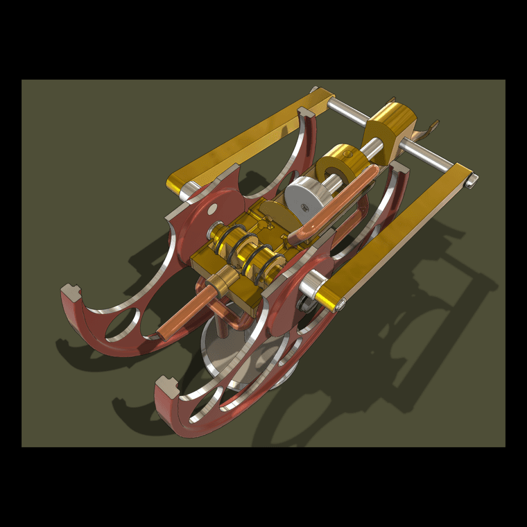
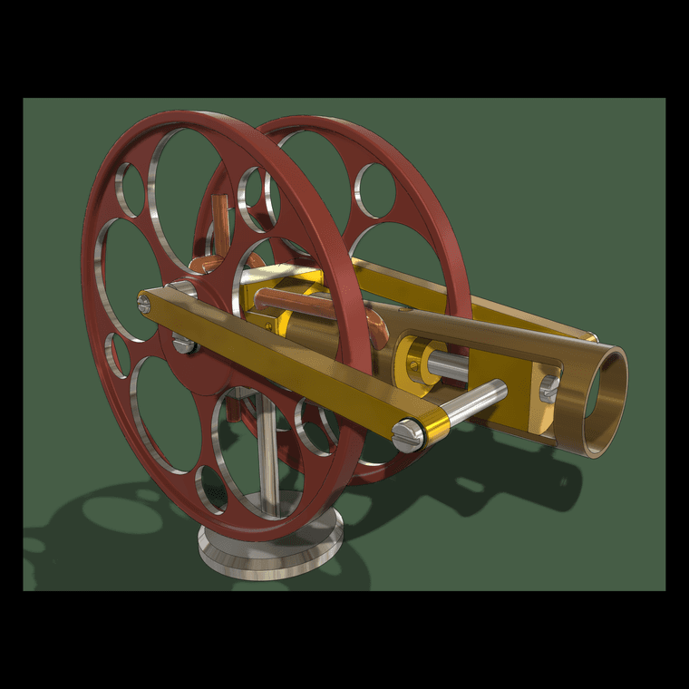
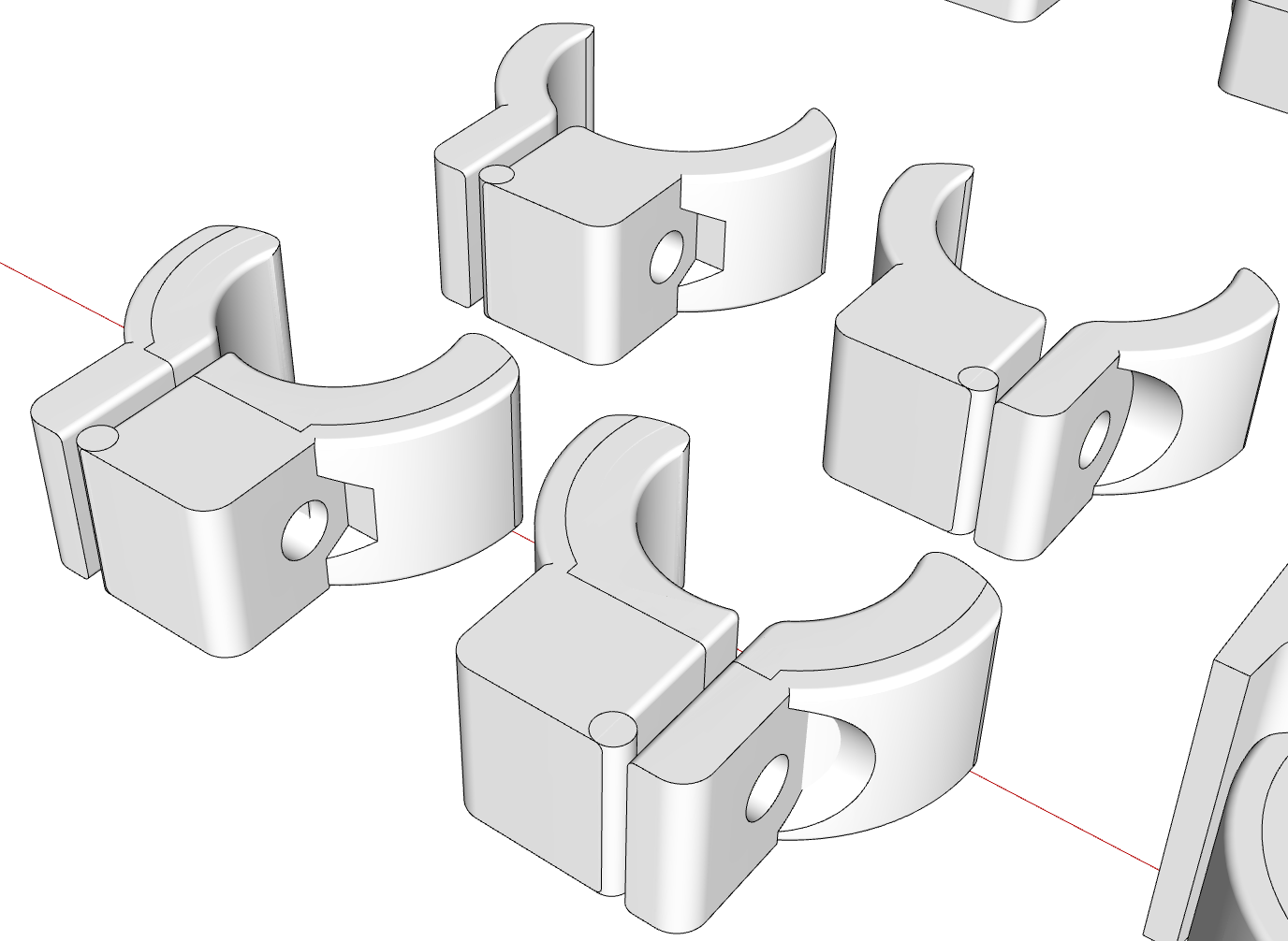
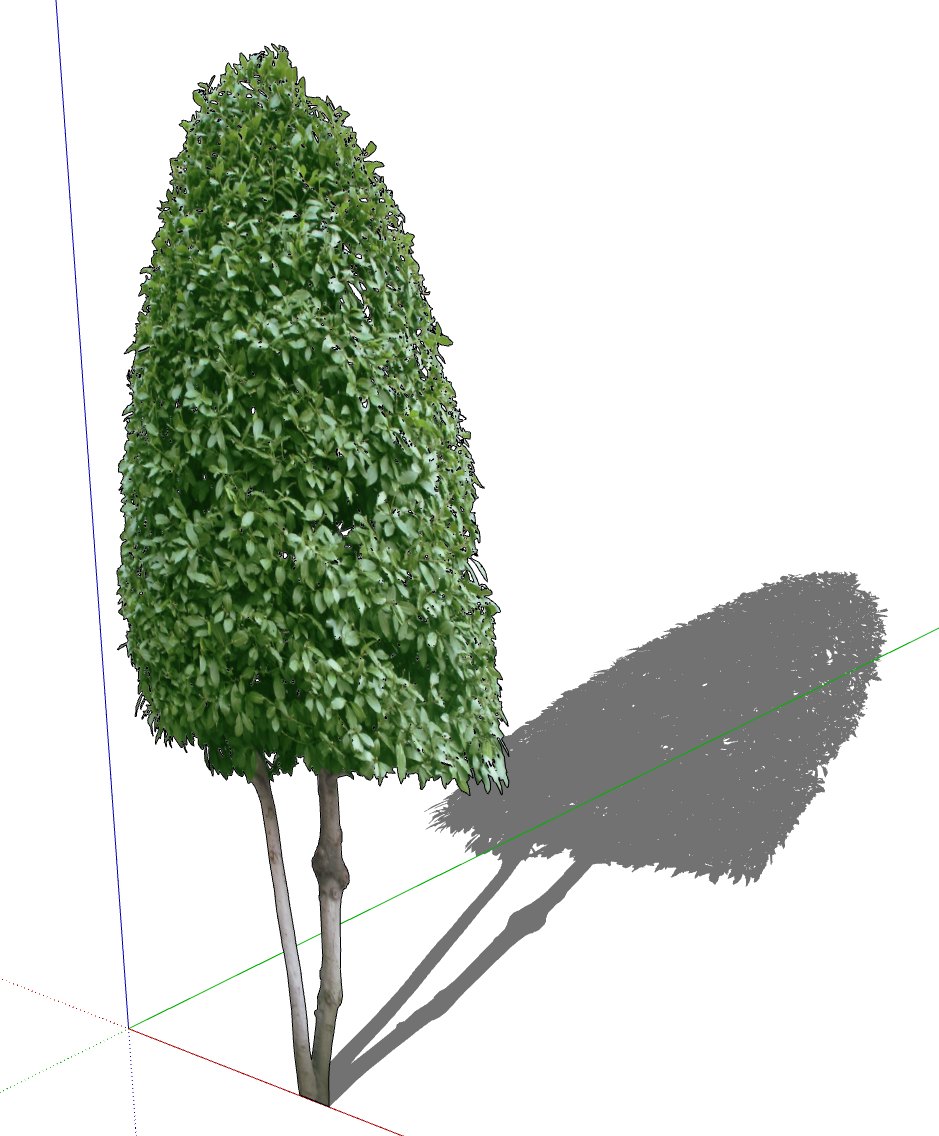
Look seriously at any entourage you insert from the 3D warehouse or other sources. Avoid high-poly components. Take the time to clean up the entourage components you add to your models or reject them and look for simpler ones. You probably don't need a detailed strainer in the bottom of the kitchen sink, nor racks and convestion fans in ovens, nor punts in wine bottles. Distill everything down to just what you need to tell your "story". Some of this may seem time consuming but I guarantee you it will pay back in time and effort saved as the project goes forward.
It also helps to turn off tags for any objects that are not visible in a given scene.
In LayOut, leave viewports set to Raster render as much as possible. Raster rendering is much faster than Hybrid or Vector. In most cases there's probably no need to render as Hybrid. At least do a test PDF export to see what you think of the output. Make sure to disable the Output Override in Document Setup>Rendering.
I would tend to use Vector rendering for Hidden Line plan and elevation scenes because dimensioning is easier but for persective views Raster is almost always adequate. If you decide you need Hybrid, save switching to it until the end and only do it for viewports that really need it.
If you like to show textures in elevation and plan views, start out by using a Hidden Line style/Vector rendering while dimensioing and while updates to the model are still likely. Change to Raster or Hybrid to display the materials before export.
If you enable Output Override to render viewports during export you can leave viewports with displayed textures rendered as raster.
Also, keep the LayOut file clean. Purge the unused references. Make sure you start every project from a clean template. Don't reuse an old project for a new one. Do not override the Camera properties for viewports. Ensure you are using the correct SketchUp reference files. Do not copy from SketchUp and paste into LayOut. If you are using a Mac it's easy to wind up inserting the backup file instead of the original work file because the only thing that differentiates the backup from the original is a tilde at the end of the filename
Last week I worked on a LayOut file for someone that was very slow. The file she sent was over 1.3 GB. It had more than a half dozen SketchUp references and images from old projects. She was just deleting the viewports and images from the pages but never bothered to purge. In her case she also had several SketchUp reference files which included the original, a backup, and in several cases she had files with multiple tildes indicating she'd not been editing the original model file. She complained that viewports weren't updating (she thought LayOut was just being slow) but it was because she wasn't editing the file linked to the viewports at all.
If you are inserting images into your LayOut projects make sure they are of reasonable size for the dimensions they are displayed on the page. There's no point in using very high res images if they are small on the sheet.
Sorry. This got longer than I intended but ...
I hope it gives you some ideas.