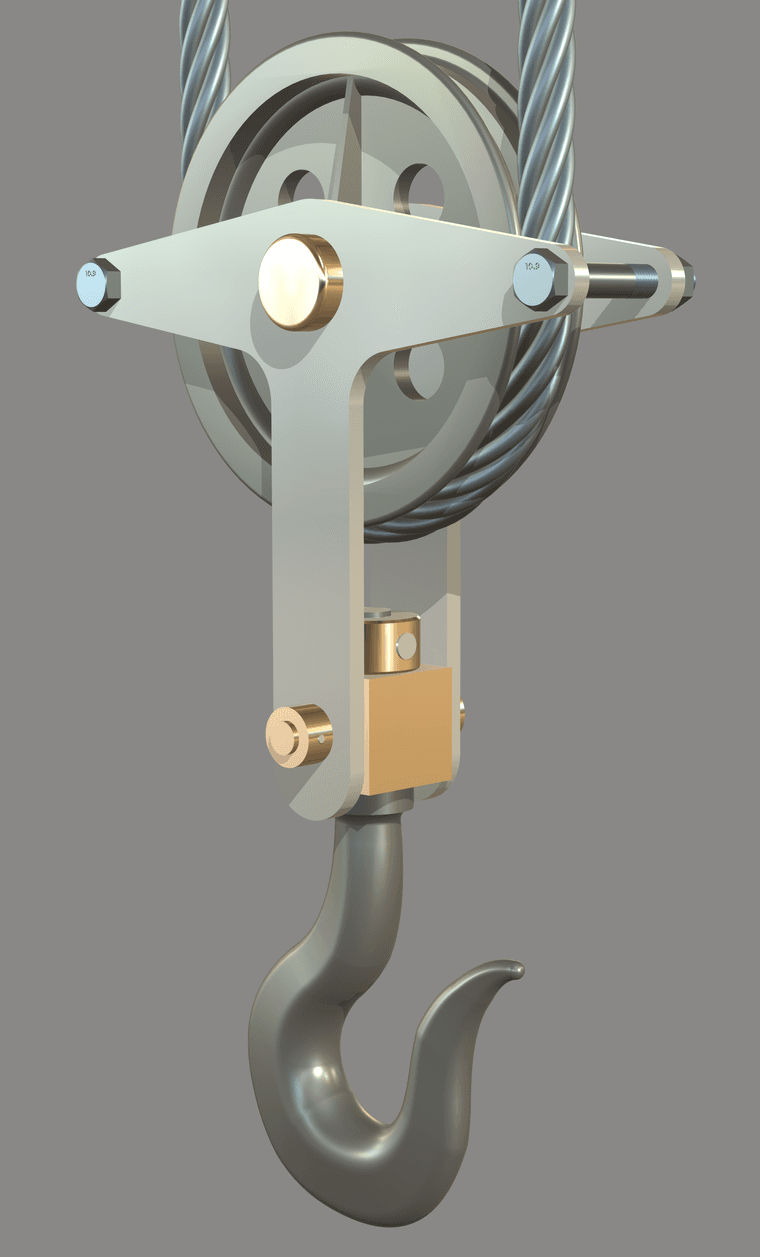
A hook on a pulley for some sort of crane or something. Based on dimensions given in an old, undated book from Spain of technical drawing exercises.
A hook on a pulley for some sort of crane or something. Based on dimensions given in an old, undated book from Spain of technical drawing exercises.
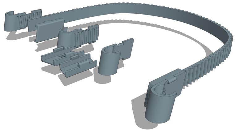
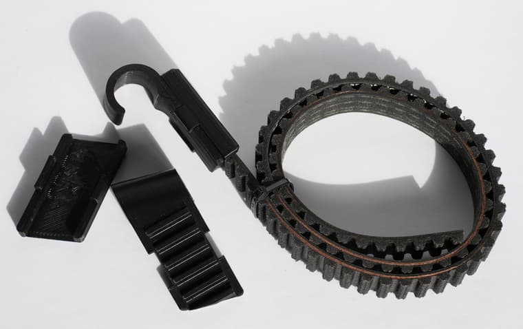
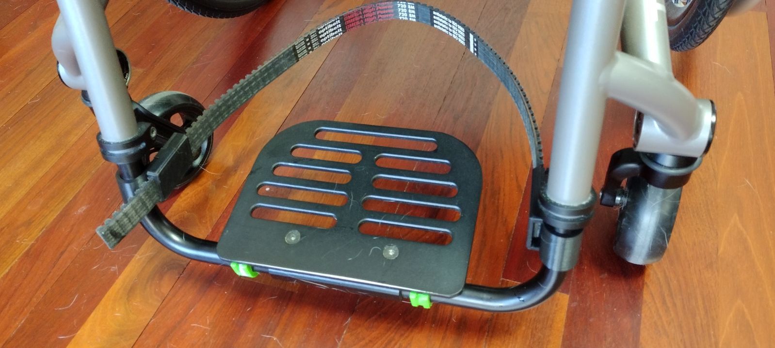
This is a heel strap for a wheelchair to prevent the user's feet from sliding off the foot plate. It's designed to install easily with no tools required except scissors to trim the strap to length. The clips with snap on covers are 3D printed to fit off the shelf polyurethane toothed belting.
From the SketchUp model.
Partially assembled.
Temporarily installed on a chair. Ignore the dog hair.
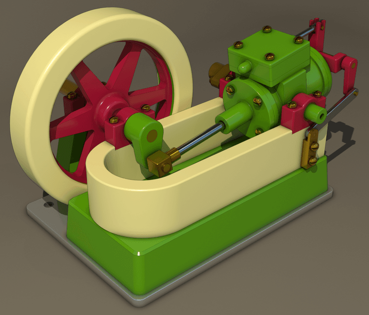
Combined a Vray render with an AO export direct from SU24.
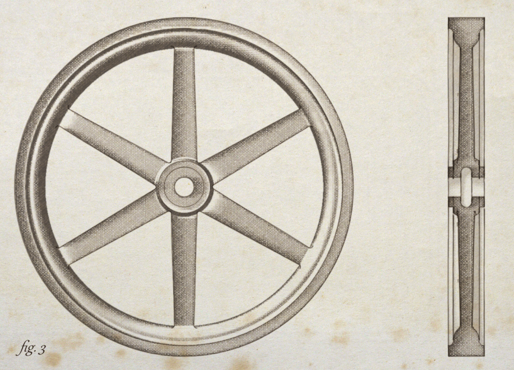
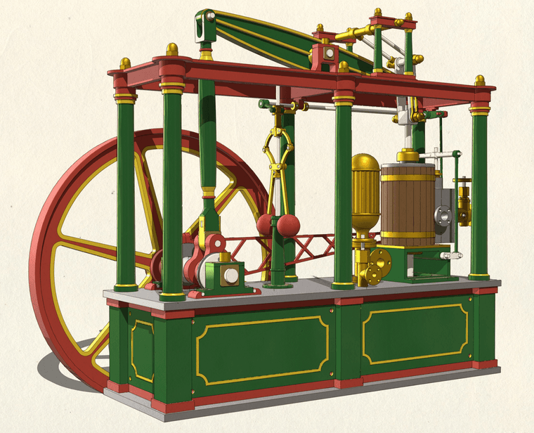
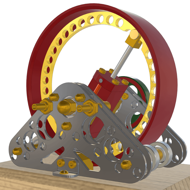
Experimenting with creating a vintage illustration style for my SketchUp models. The flywheel is based on dimensioned drawings in a textbook from 1897.
This one is called Lady Stephanie. I don't know who the real Lady Stephanie was but if she was anything like this engine, I'm guessing she was kind of ornery and hard to please.
After putting her aside I did another engine today. This is a a little crankless engine.
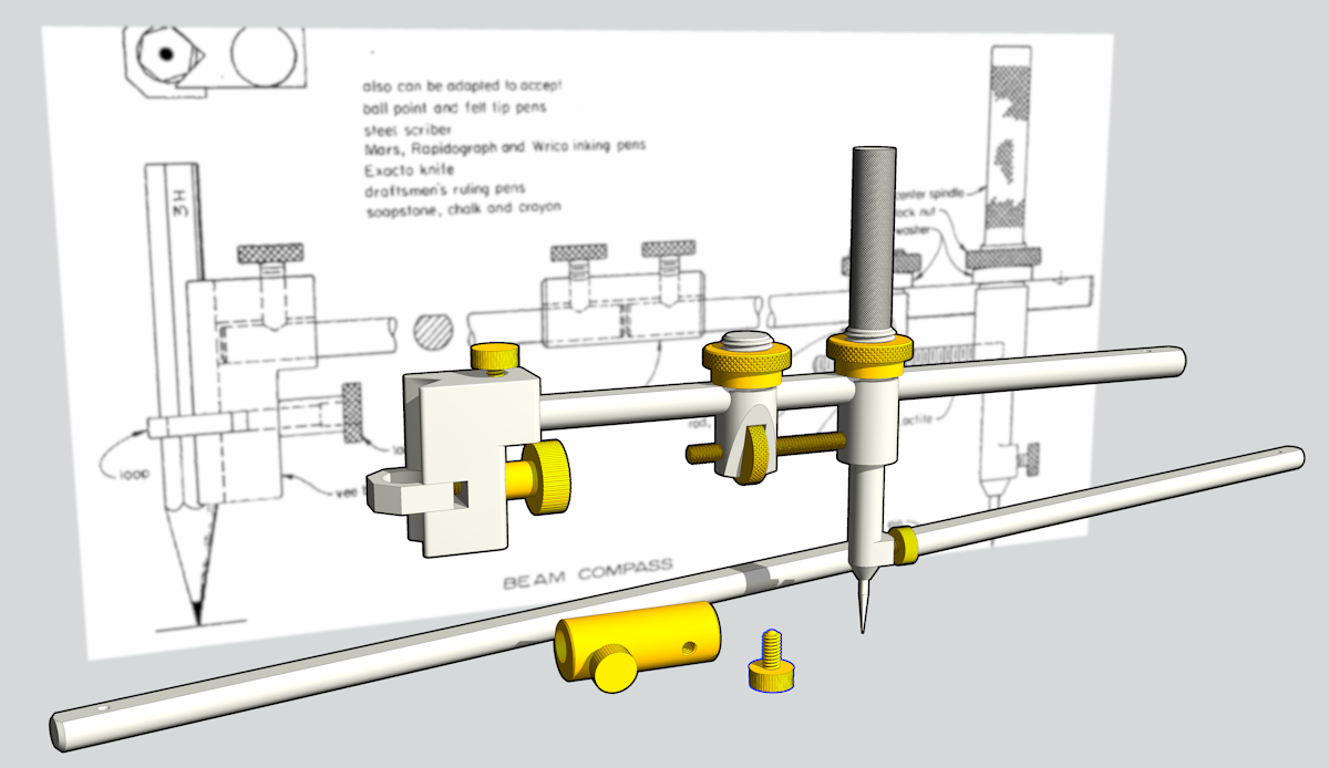
A model of what is probably the first micrometer ever made. It's dated England about 1776 and attributed to James Watt although evidence shows it likely wasn't made by him.
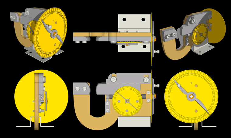
A larger version of this image is available here.
All the screws are made and holes threaded. 28 component definitions, all solids.
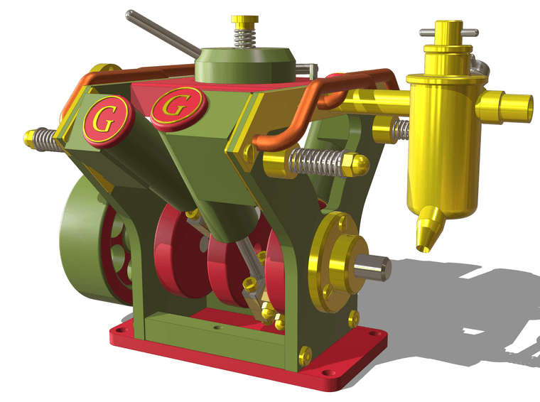
Funny guys!
And here's another one. A little 4-cylinder oscillating engine. As usual, all base level components are solids.
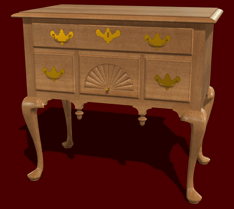
This is from a model I initially made 11 years ago for shop drawings. I pulled it out recently to do a bit of refining in SU2025.
Sounds like you didn't install SketchUp 2026 correctly. On Windows, correct installation requires right clicking on the downloaded installer and choosing Run as administrator.
Note that the Large Toolset cannot be modified. You can modify other native toolbars or create your own.
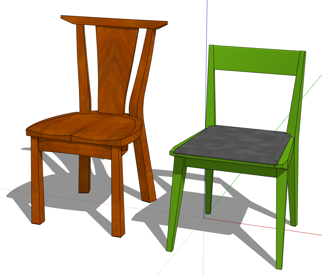
I only know the blue axis, the height, because many catalogs only list the height.
Proportionally scaling the chair based only on its height most likely won't yield the right dimensions for depth and width, though. If, for example I proportionally scale the chair on the left to be the same height as the one on the right, the seat would end up both too narrow and too short front to back.. Scaling proportionally would also result in reducing the seat height which wouldn't be correct for the chair.
In your example where did you get the 3D models of the green chair?
but I don’t know which formula to use, and I can’t figure it out.
How about using the same tool to interrogate one of the other chairs for dimensions and then enter those in the panel for the green one. It may not be appropriate to change all of the dimensions with any form of Scale tool anyway.
I’m attaching this image where the green staircase is out of scale
Those are call chairs where I come from. 
I haven't had any freezing or other weird behavior with Clothworks. It works as expected for me.
Which version do you have installed? What operating system? What SketchUp version? What version of the Sketchucation ExtensionStore do you have installed?
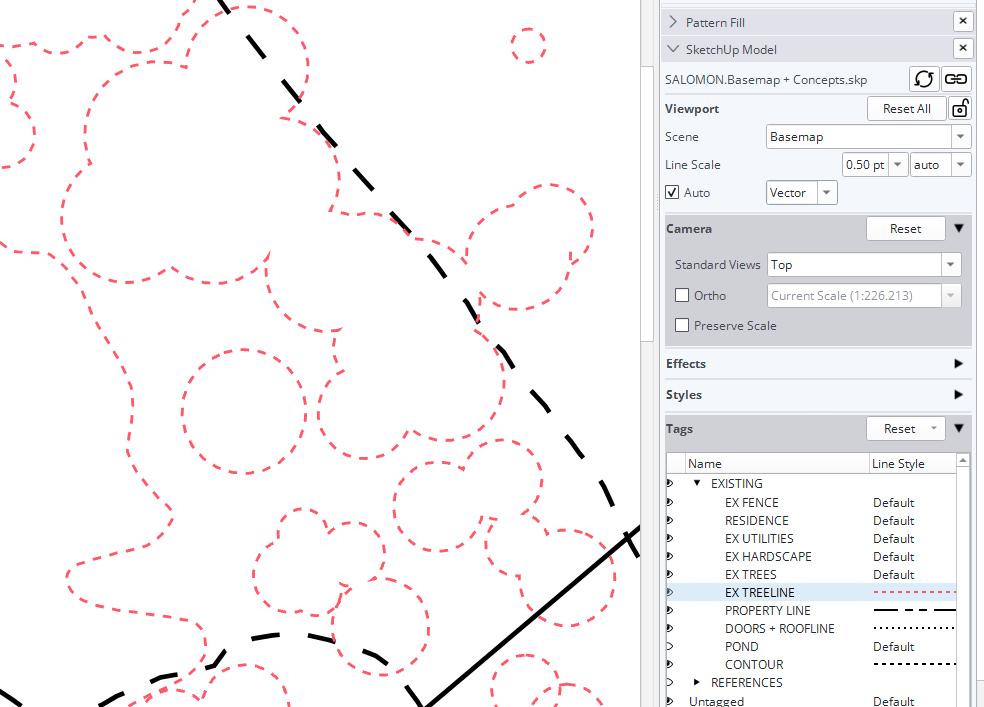
@adrienneverdefinegardens0131 I presume when you refer to groups in your post you are talking about Tag Folders. There have been a few reports of other users not being able to edit the color or dash style for tags in tag folders in SketchUp/LayOut 2026. I've been doing some testing and I'm not having any difficulty, though. Even in your file I can change the color and other parameters for dashes in LO. Here's an example in which I changed the color and scale of the EX TREELINE tag.
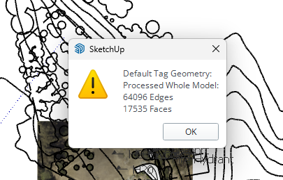
I see incorrect tag usage in your model. ALL edges and faces should be created and remain untagged. Tagging the geometry can create a number of problems including adjusting the dash styles as well as colors. This is the result of correcting the tag usage.
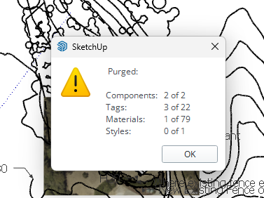
Purging unused content in the model.
Although not related to the dash and color thing, I notice you've overridden the Camera properties for the viewport. This can be a problem especially in cases where you've added labels and dimensions linked to the viewport.
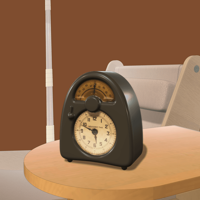
@Rich-O-Brien I like that clock, too. Once in a while I see them listed for sale but they are pretty dearly priced.
and the edges are morphing into something weird
What do you mean by that? The only thing I see is that the rim edges top and bottom are softened heavily.
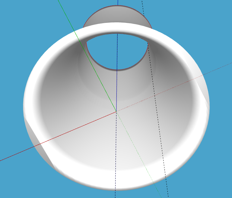
Easily fixed by triple clicking on the shape with Select then right clicking and selecting Soften/Smooth.
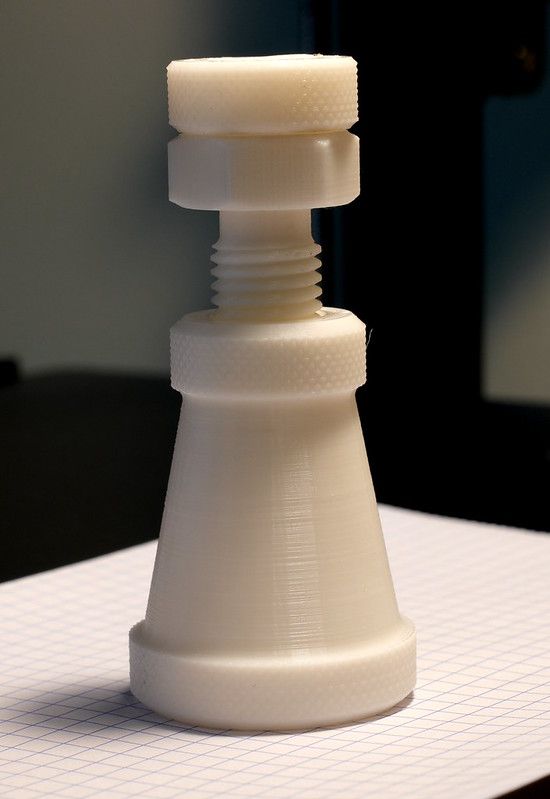
There are several other extensions out there that can make screw threads. Look at EP Fasteners or Draw Whorl from the Extension Warehouse.
I model them using Curve Maker and Upright Extruder.
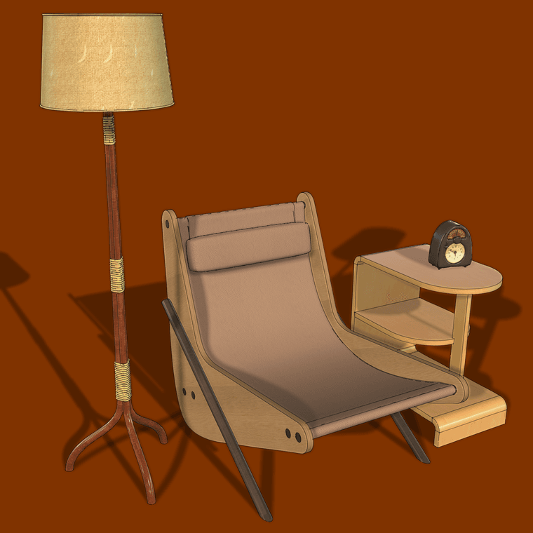
Thonet-inspired floor lamp, 1920s, Brazilian chair, 1950s, Finnish designed shelf unit, 1930s, and Isamu Noguchi "Measured Time" clock, 1932.