đŸ«› Lightbeans Update | Metallic and Roughness auto-applied in SketchUp 2025+ Download
  • Solids for 3D Printing

    5
    3
    2 Votes
    5 Posts
    169 Views
    Dave RD
    @Rich-O-Brien thank you. The bolts tighten up enough for what these need to do but I probably should have extended the that side so I could complete the hex recess. I expect then I could tighten the knob enough to break the clamp.
  • Extend a rod with with screw thread

    2
    1
    0 Votes
    2 Posts
    98 Views
    Dave RD
    What version of SketchUp are you using? That will help us to know what tools you have available. What have you done so far? These are all M6 for 3D printing. [image: 1762271282620-screenshot-11_4_2025-9_47_02-am.png] Here's an internal M6 thread. [image: 1762278826049-screenshot-11_4_2025-11_52_53-am.png] I modeled all of these using the method I showed in the video I posted here: https://community.sketchucation.com/topic/164552/help-with-a-thread/20?page=1
  • Strange corners

    6
    1
    0 Votes
    6 Posts
    993 Views
    L
    Overhang is 45 so no support needed, support at ideamaker gave me a gcode for xy and it worked good To be honest the raise 3d machines can’t compete with the bambus
  • Any good tutorials on BEVEL gear design in SU?

    20
    0 Votes
    20 Posts
    2k Views
    jgbJ
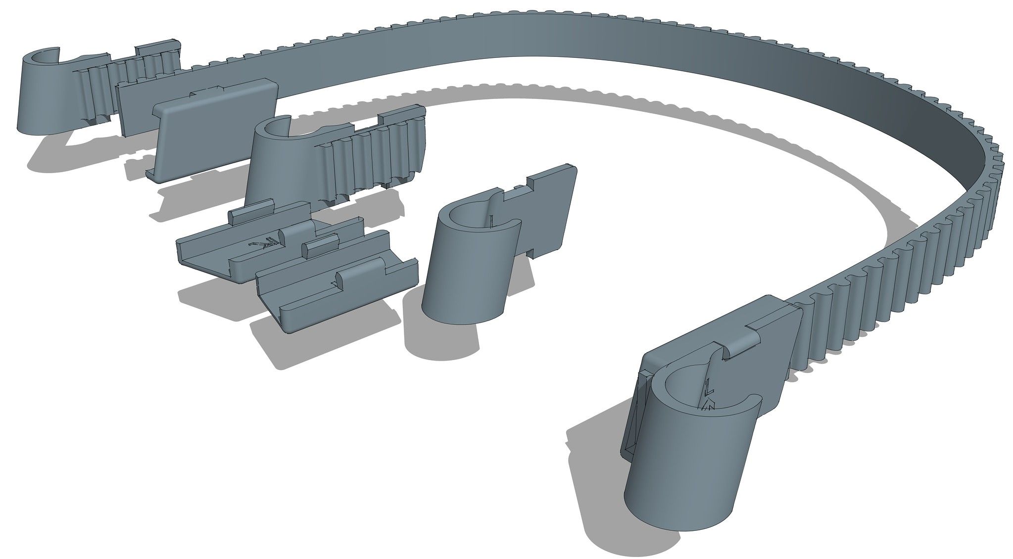
    Spent the better part of yesterday getting this gear right (I hope). It is a 24 tooth bevel gear 22.5 mm diam (drawn in centimetres). Gear E in my diagram above. SPGears created a fairly close model. I had to compare that model to my desired cross section and manipulate it into shape. I had to get rid of the overhangs on each tooth to avoid any supports. That was the tedious part. (I'll show how later today) Thankfully SPGears creates each tooth as a circular array of one tooth, so editing is relatively easy. Then I had to make a single generic hub as the 5 gears, plus the other smaller gear (scaled down a bit) have different hubs. That part was far easier. An SPGear is actually a group of 2 nested groups, the set of teeth, and the hub, done in a strange way, but hey, it works. I made it a component of the 2 nested groups. To make sure the gears mesh correctly (fingers crossed) I duplicated the SPGear and turned it 90 deg. I drew an axial line to the vertex within the component for alignment purposes. I then turned it 90 degrees and mated them at the vertex. I also rotated the vertical gear 7.5 deg (24 teeth) to properly mesh the 2 gears. That resulted in a large gap between teeth. By eye I moved the vertical gear along blue and red axis (equally) till I got a nice mesh with a bit of play. Then adjusted (shortened) the vertex end of the axial line accordingly. There were tiny overlaps. So I had to scale the 2 face ends of the teeth a bit to clean up the mesh. Only after all that was I able to redraw the large end to eliminate the overhangs. [image: 1760119413639-24-tooth-bevel-gear.jpg] I cannot yet print a pair to test as I do not yet have a printer (long story, and it's not the $$$) Later.......
  • A Recent 3D Printing Project

    sketchup 3dprint
    12
    3
    6 Votes
    12 Posts
    969 Views
    Dave RD
    It's to prevent wear and damage to the anodizing on the chair's axle tube. The lift is designed to be very generic and so it's not really an incompatibility thing. The lift is intended to pick the chair up by the 19mm aluminum cross tube on the backrest but that's not a real strong part to hang the entire weight of the chair from, especially on rough roads. I designed and printed some hooks to lift and support the weight of the chair by the axle tube. In the picture here https://flic.kr/p/2peh56W, there's some white foam tape that was used temporarily. It's not very durable, though.
  • infill in open tube

    5
    0 Votes
    5 Posts
    298 Views
    L
    [image: 1748383936810-4b7ab5ae-f601-42af-a676-ccd076cf68b1-image-resized.jpeg] This is what I’m trying to make in TPU
  • 3D lamp designing tips

    3
    8
    1 Votes
    3 Posts
    132 Views
    A
    @Rich-O-Brien thanks
  • Part not printed as drawn

    Solved
    5
    2
    0 Votes
    5 Posts
    367 Views
    A
    @Dave-R Thank you!
  • Open areas and rounded surface

    31
    2
    0 Votes
    31 Posts
    952 Views
    A
    obviously not. mysterious!
  • Fixing Stuff Around the House

    3
    3
    2 Votes
    3 Posts
    285 Views
    Dave RD
    @Rich-O-Brien yeah. I also wonder how long they will last. Actually we're replacing all the windows in our house this year so this one doesn't need to last a real long time. A neighbor down the street has the same kind of windows and has a number of broken ones so I'll print some for him, too. I have no idea but my guess is they were used on another type of window, too.. And maybe in a different way that would make the the curves, notch, and second set of holes required. Those features certainly aren't used in the application on our windows. I like the new version better, too. Thanks.
  • All parts are exported as .stl instead of only the selected

    5
    0 Votes
    5 Posts
    325 Views
    A
    @Rich: that's exactly what I did, but it didn't prevent exporting everything!
  • 3D Printed Screw Threads

    23
    0 Votes
    23 Posts
    683 Views
    Dave RD
    I would like to do something to smooth it out but it's fine as it is. The threads have a fit typical of metal ones but it won't whistle. I think because the PLA doesn't resonate like bronze, brass, or iron would. I expect I could run steam through it. Once.
  • No Screw Threads This Time

    3
    0 Votes
    3 Posts
    269 Views
    Dave RD
    @rich o brien said: Are the chairs known to fail over time when lifted by its intended bar? I've seen broken backrest frames before although not specifically related to this model of lift. The welds and the hinge mechanisms are clearly not designed to support the about 13 Kg weight of the chair all the time, not to mention the added g-load when traveling over bumps on the roads. @rich o brien said: If you patent it I've the perfect name for it... Axle RoseUp Very good. If I go that route I'll give you a cut of the profits.
  • 3d Printing Architectural models

    3
    0 Votes
    3 Posts
    278 Views
    R
    @gullfo said: if the imported objects are "solids" then you could use "outer shell". This is exactly what I was looking for. Thank you.
  • 10 Houses in 24 hours 3D print

    sketchup
    41
    0 Votes
    41 Posts
    25k Views
    R
    Is this possible even because it seems difficult to execute especially when it comes to quality and the aetheticness of the sketch. As i have been into this category since 2003 and never found these statements.
  • New 3d Machines Unveilings & Pens, Scanners, Elements Idems

    sketchup
    993
    0 Votes
    993 Posts
    284k Views
    S
    3D printing, desktop 3D printing machine, rapid prototyping, additive layer manufacturing, digital manufacturing of objects, ... these are all different and confusing terms of an emerging technology that we often encounter on the Internet and in media reports. All the tech world geeks, engineers, architects, inventors and designers are talking about the complex technology of the 3D printer and it is even mentioned as a new industrial revolution. Ű·ÙˆÙ„ ŰčÙ…Ű± ŰłŰ±Ű·Ű§Ù† ۧ۳ŰȘŰźÙˆŰ§Ù†
  • A 3D "Spacer" to fill gap between shower wall and downspout?

    1
    0 Votes
    1 Posts
    376 Views
    No one has replied
  • How to convert STL to 3MF?

    13
    0 Votes
    13 Posts
    532 Views
    Dave RD
    @involute said: Model in inches, export STL in mm That's not what I was telling you to do but if it works for you, great.
  • Make a barely visible frame that matches my 3D print frame?

    3
    0 Votes
    3 Posts
    234 Views
    ?
    If you want to try going with guides route, one easy way of making a fixed length guide is to start on the origin, then pull out on green and make it the length of your build plate. Now you easily see the cpoint but the tail is hard to see when it's on axis, so just move the guide off axis a bit for visibility. Now array 3 more copies. But since you can't inference to the tails, easier to array in a 2 x 2 grid that is sized to your build plate. Anyway, get the cpoints in place first any way you can, then rotate the tails in place later, just my opinion, there would be 50 ways of doing this. Then make them a group and move the corner back to the origin. Just a thought.
  • Export stl

    sketchup
    8
    0 Votes
    8 Posts
    16k Views
    T
    Upgrade your home's appearance with our top-notch decorating services and products that are sure to impress Homephix cares about your budget as well. For your home decoration your should visit homephix.co.uk/

Advertisement