OK, I'll try meters next 3D printed model.
Again, thanks for the help and advice.
jgb
OK, I'll try meters next 3D printed model.
Again, thanks for the help and advice.
jgb
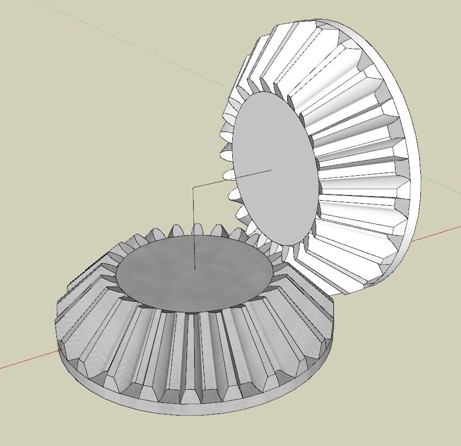
Spent the better part of yesterday getting this gear right (I hope). It is a 24 tooth bevel gear 22.5 mm diam (drawn in centimetres). Gear E in my diagram above.
SPGears created a fairly close model. I had to compare that model to my desired cross section and manipulate it into shape.
I had to get rid of the overhangs on each tooth to avoid any supports. That was the tedious part. (I'll show how later today)
Thankfully SPGears creates each tooth as a circular array of one tooth, so editing is relatively easy.
Then I had to make a single generic hub as the 5 gears, plus the other smaller gear (scaled down a bit) have different hubs. That part was far easier.
An SPGear is actually a group of 2 nested groups, the set of teeth, and the hub, done in a strange way, but hey, it works. I made it a component of the 2 nested groups.
To make sure the gears mesh correctly (fingers crossed) I duplicated the SPGear and turned it 90 deg. I drew an axial line to the vertex within the component for alignment purposes. I then turned it 90 degrees and mated them at the vertex. I also rotated the vertical gear 7.5 deg (24 teeth) to properly mesh the 2 gears. That resulted in a large gap between teeth.
By eye I moved the vertical gear along blue and red axis (equally) till I got a nice mesh with a bit of play. Then adjusted (shortened) the vertex end of the axial line accordingly.
There were tiny overlaps.
So I had to scale the 2 face ends of the teeth a bit to clean up the mesh. Only after all that was I able to redraw the large end to eliminate the overhangs.
I cannot yet print a pair to test as I do not yet have a printer (long story, and it's not the $$$)
Later.......
@alexpacio2013
Thanks. I know what you mean to be retired and have "plenty" of time on your hands. Even so, I have been working on this concept for over 7 years and the model to prove it will work for about 4 years now. Plenty of time but plenty of distractions as well.
My model design is complete, except for the actual gears design and some final wire routing.
However, if you have expertise in trigonometry and Excel I could use some help in some spreadsheets I cannot wrap my head around.
The main spreadsheet is a simulation of the model both for proof of concept, animated demonstration/presentation and design of some part sizes for a real life-sized device.
I would need you to commit to an NDA to bring you on board, as I have about 7 patents to reveal for you to help me..
@alexpacio2013
Thanks, but there is nothing about my model that has predefined printed parts. Other than motors, screws, bearings and some electrical parts, all of it is a unique design.
I have visited this site before and it has a lot of neat stuff, but nothing appropriate to my model.
Thanks for the reply.
I will be open (to a limited extent) about the model I need to build. Can't show all due to patent reasons.
I am using a Centimetre Drawing unit which will translate to Millimetres when printed on a Snapmaker A350 (when I get it).
It has a print resolution of .05mm in XY and .12mm in Z axis. So my minimum line segment length has to be .05mm or greater.
So drawing in Centimetres or Meters makes little difference, except I can mentally visualize in Centimetres better.
The actual dimensions of the gears are determined by several factors, but can vary a bit (1 or 2 mm) if and as needed. However the ratios are firm.
All are bevel gears, ranging in size from (about) 20mm (printed), 25mm, 50mm, 140mm and 280mm (see drawing). I usually go by outside diameter rather than pitch diameter, but I can adjust to one or the other if needed.
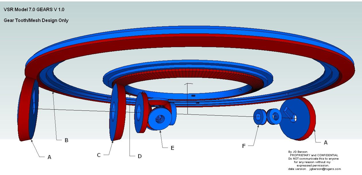
There are 6 types of gears, A to F.
A - About 50 mm diam printed. There are several of these same gears, but I only show 2. The tooth count really does not matter and I will adjust as needed.
B - The Main ring gear is about 280 mm diam meshing to gear A. Again, tooth count really does not matter but MUST be an even count.
C - MUST be the same diameter and tooth count as A, but the bevel angle is different. There is only 1 in the model.
D - Is a smaller ring gear meshed only to gear C. The diameter and tooth count MUST be EXACTLY 1/2 that of gear B. (140 mm diameter) This is critical.
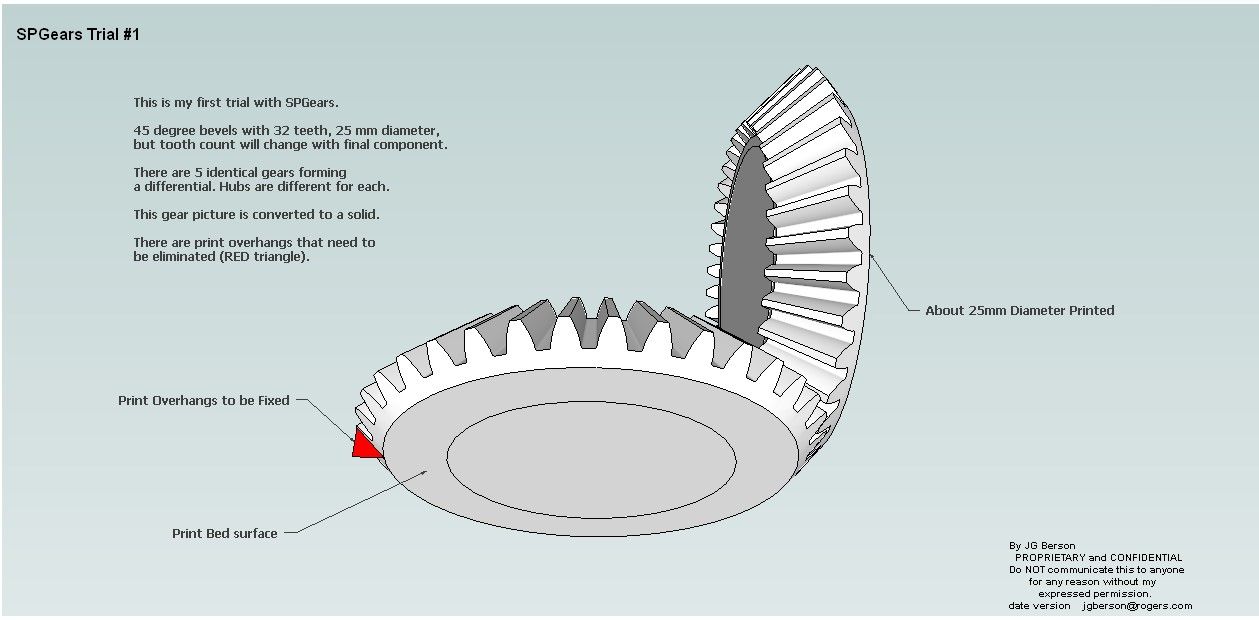
E - Is a "standard" 45 degree bevel gear, about 25 mm diameter and no specific tooth count, but not too fine. There are 5 of these same gears forming a differential.
*Ignore the unlabelled gear to its left. That is a whole other problem to solve. It is a worm gear with diam and tooth count to be determined by some complex math once these other gears are known as well as other factors.*
F - Are also 45 deg bevel gears, same as gear E but smaller, about 20 mm diameter. There are 6 in the model.
So the 2 really difficult gears to design are gears B and D in order to mesh properly with gears A and C respectfully..
FYI; Gears A, C and E are connected with concentric shafts and form the 50% RPM reduction needed between gear A and C.
When I first started SPGears, I created a 45 deg bevel gear with some arbitrary values, as I still do not full understand its dialog box.
I played around a bit to figure what it was made of; (lots of components) then simplified it to a solid and removed unnecessary soft lines.
But it also produced gear teeth with lots of tiny overhangs (in red) where a lot of work will be necessary to remove support material. I will modify the single gear tooth component to eliminate that overhang.
I would appreciate if you could fully explain the SPGears dialog box as some of the terms are not reflected in other documentation.
Thanks. It loaded OK, and I made test gears OK. Makes nice looking gears.
I figured out how to reduce the lines count and make it solid.
But now I need to make gears to very specific sizes and my foggy brain cannot interpret the dialog box to do it beyond a simple diameter and tooth count.
Also, it produces gears that will be difficult to print; too many overhangs equates to a lot of tiny supports to be removed, and many line lengths are smaller than the printers print resolution. The gears in your diagrams above are far closer to what I need, but I can tweak the SPGears output for that, given each tooth is a component.
Quite frankly, I do not fully understand gear design, beyond number of teeth, diameter (pitch radius), face width and bevel angle.
I really need some tutorial in understanding the SPGears dialog box, and what "Diametral = xx" means.
I have basically 2 types of 90 degree straight bevel gears to make. One pair of same everything; 25mm diameter 24 teeth (simple) and two sets where the diameter ratios are 50mm:280mm and 50mm:140mm. Those are the hard ones to get properly meshed teeth with SPGears.
I can probably play around to get them to work once I understand SPGears dialog box.
Can you help me with that?
@Dave-R
I'll give it a try.
Thanks
@Dave-R
Thanks, but nearly nothing I design has a standard base that I can use. Believe me, I looked.
jgb
@Rich-O-Brien
Thanks. Not sure that will work for me in SU 2015. Info says the gears are mainly for SP and may not be OK if 3D printed.
But I will try it later this week.
jgb
I need to design several sizes of bevel gears for a working model that will be 3D printed.
Quite frankly, all the design tools I have found are for Excel, Fusion or Solidworks or detailed engineering that now baffle my 80 year old brain.
Are there any good simple tutorials based on Sketchup (2015) that will produce a simple gear tooth profile out there?
The gears range from 16 mm diam to 270 mm diam. All are 90 deg bevel. None subject to strong forces.
Or, I can define each of the 6 different sized gears and someone gear savvy among you could graciously design for me. If so, I'll post here the SU file of the gear train and any other details one might need.
I only need the tooth design. Hopefully the same shape can be used for all 6 gears. The gear hubs I have covered.
Thanks, jgb
OK, I'll try meters next 3D printed model.
Again, thanks for the help and advice.
jgb