I want AI to mow the lawn, shovel the snow, do the laundry and the dishes. Leave the creative stuff to humans.
Oops, your profile's looking a bit empty! To help us tailor your experience, please fill in key details like your SketchUp version, skill level, operating system, and more. Update and save your info on your profile page today!
Check out Febhouse | New extensions for Shadow Analysis in SketchUp Download
Posts
-
RE: ALL THINGS AI
-
RE: SCFLicense: Extension Licensing on Sketchucation
@Mikulassladek said in SCFLicense: Extension Licensing on Sketchucation:
Do I have to pay for it or is it stilll free
FWIW, FredoCorner has required a paid license since 2021.
If you never purchased a license for it the license couldn't have been removed.
-
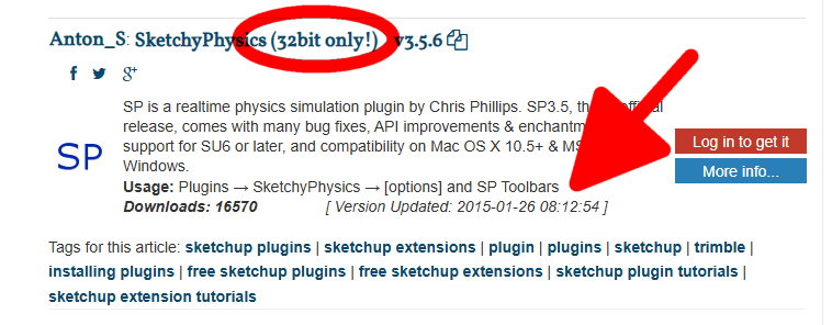
RE: SketchyPhysics 3.5.6 (26 January 2015)
@Joeyinsully Sketch Physics hasn't been updated in over ten years. It hasn't worked in newer versions of SketchUp for years so it's not surprising that it doesn't work in SketchUp 2026.
-
RE: [Plugin][$] RoundCorner - v3.4a - 31 Mar 24
@wpns that looks similar to an issue related to certain Mac GPUs in which dimensions were inverted with older versions of SketchUp. In that case it was found that if a fix was to come it had to come from Apple. I don't know if it ever did.
Effectively the Mac OS has evolved out from under that old version of SketchUp. As long as you continue with SketchUp 2017 you'll probably have to live with weird stuff. Many users have reported repeated crashes and other unwanted behaviors with old versions of SketchUp. My guess is it won't get better.
-
RE: SCFLicense: Extension Licensing on Sketchucation
@ntxdave said in SCFLicense: Extension Licensing on Sketchucation:
OK, I thought all of my Fredo6 licenses were perpetual but maybe not.
They are perpetual but if you never purchased a license for FredoSketch then that doesn't come into it. If the license isn't showing up in the list that Rich linked to, it's probably safe to say you didn't buy a license.
-
RE: SCFLicense: Extension Licensing on Sketchucation
The only thing I see in your screenshots is that you have the extension installed and that the trial period has expired. Nothing that shows you have purchased the license, though. The Extension Manager doesn't say anything about whether or not you have a license.
-
RE: SCFLicense: Extension Licensing on Sketchucation
@ntxdave said in SCFLicense: Extension Licensing on Sketchucation:
I am not seeing the FredoSketch license
Did you purchase a license for FredoSketch?
-
RE: Sketchup and Miniature Modelling STLs
@Grizzly256 said in Sketchup and Miniature Modelling STLs:
No, i kept them to millimeters.
I did include that information a couple of days ago.
@dave-r said in Sketchup and Miniature Modelling STLs:
Set model units to meters and leave the model at the larger size.
What happened when you export after setting the model units to Meters?
-
RE: Sketchup and Miniature Modelling STLs
@Grizzly256 did you change the SketchUp model units to meters before exporting the .stl file?
-
RE: Sketchup and Miniature Modelling STLs
You have the Softening/Smoothing set ridiculouslu high for what you're modeling.
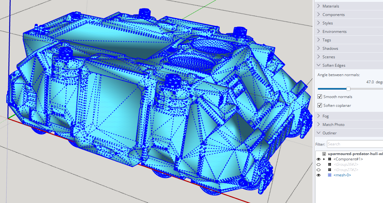
Select all of the edges and set the angle to 20°.
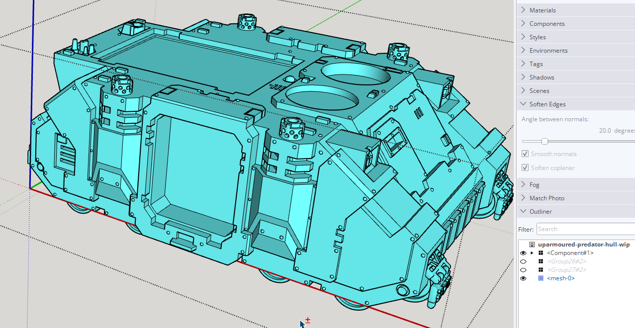
There's a lot of unneeded triangulation in the model due to the face it starts from a .stl file. That's what .stl files are.BTW, if you plan to 3D print the other thing in your model you'll need to correct the face orientation. There should be no exposed back faces (shown in blue). The back faces are all to point at the print media. White front faces are toward air.
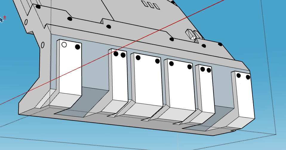
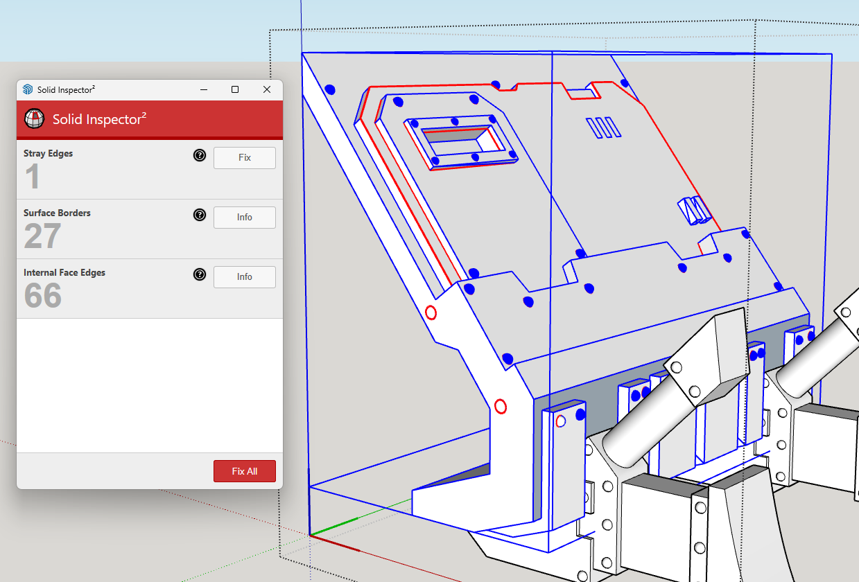
You also have some other issues to repair before it is 3D printable.
-
RE: Sketchup and Miniature Modelling STLs
@Grizzly256 said in Sketchup and Miniature Modelling STLs:
just the 5 day limit is annoying.
It's not a free extension. If you need it and it saves you time, it's worth paying for. The alternative is to do what it does manually.
@Grizzly256 said in Sketchup and Miniature Modelling STLs:
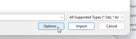
it doesnt give me an option to set the import unit when doing so. I just click File-Import-Select File-Import. I never get the option to set import units.
You can get the option to set the import units. After selecting the .stl and before clicking Import, click on the Options button.
@Grizzly256 said in Sketchup and Miniature Modelling STLs:
I cant figure why i cant find which settings to turn of to bring it back to normal.
What's normal? Looks like you just need to adjust edge softening. Share the .skp file so we can see exactly what you are working with.
-
RE: Sketchup and Miniature Modelling STLs
If you set the import units to meters the model will import as if millimeters are meters. and you'll be less likely to have issues with holes in surfaces. Rich's suggestion to use Skimp is a good one for simplifying the geometry after you have the .stl imported.
Set model units to meters and leave the model at the larger size. When you export the .stl again it should be in meters but will open in the slicer in millimeters. Look at existing threads in this category to see some other examples I've shown.
-
RE: [Plugin Library] LibFredo6 - v15.9b - 21 Apr 26
@GavinG do you have the latest version of the Sketchucation Extension Store installed?
-
RE: [Plugin] Animator - v4.6a - 18 Dec 25
The scenes called "Animation" and "Csonclusion" [sic] are set to Parallel Projection.
-
RE: Share models
@ntxdave said in Share models:
Right now all I was trying to do is see if this link worked. I need someone to verify that they can access the file.
The link takes me to an empty DropBox folder.
-
RE: Share models
@ntxdave said in Share models:
OK, DropBox has a monthly subscription
They have a free option as well.
@ntxdave said in Share models:
Can I or How would it be to use Trimble Connect?
Yes. You can share the file with Trimble Connect, too.
-
RE: Share models
@ntxdave upload it to DropBox or Google Drive and share the link.