Part not printed as drawn
-
Hello,
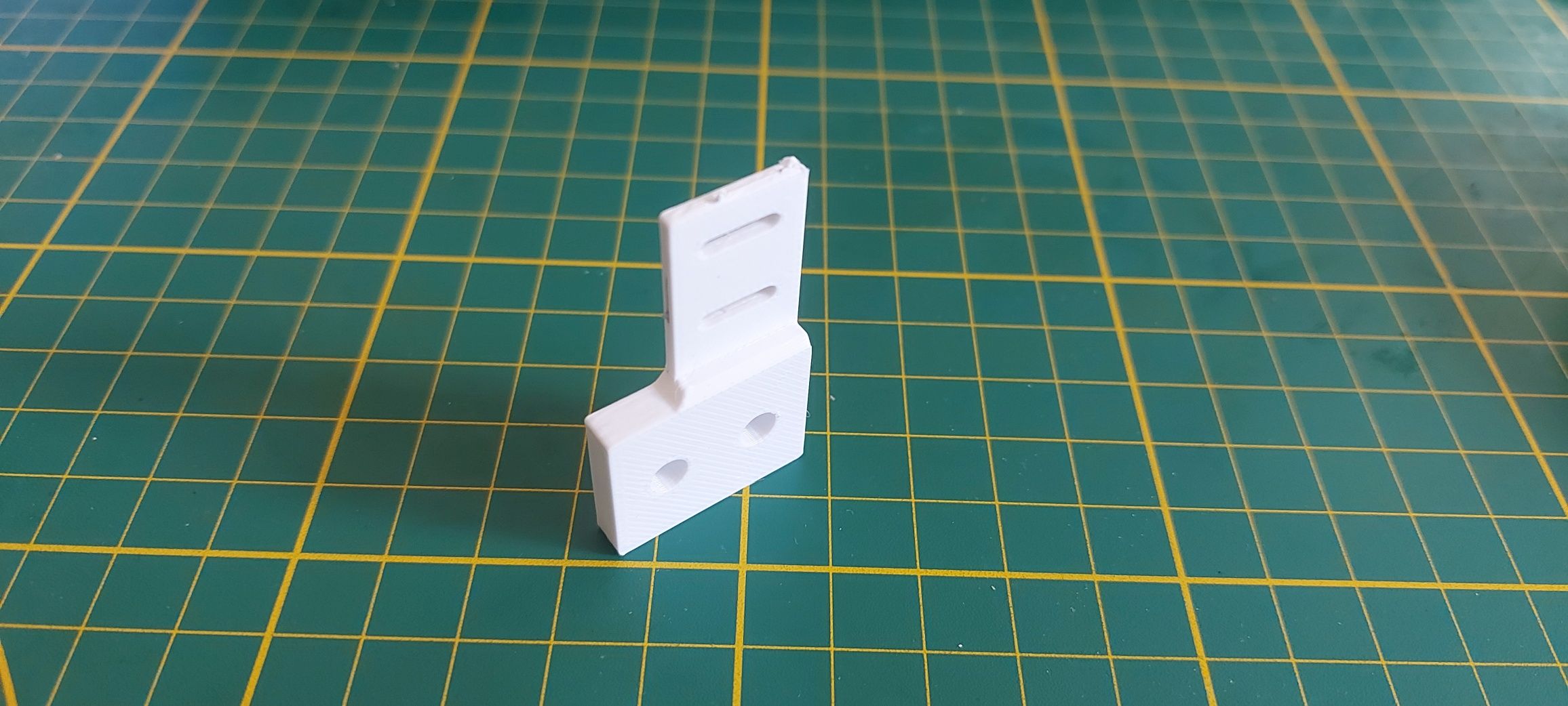
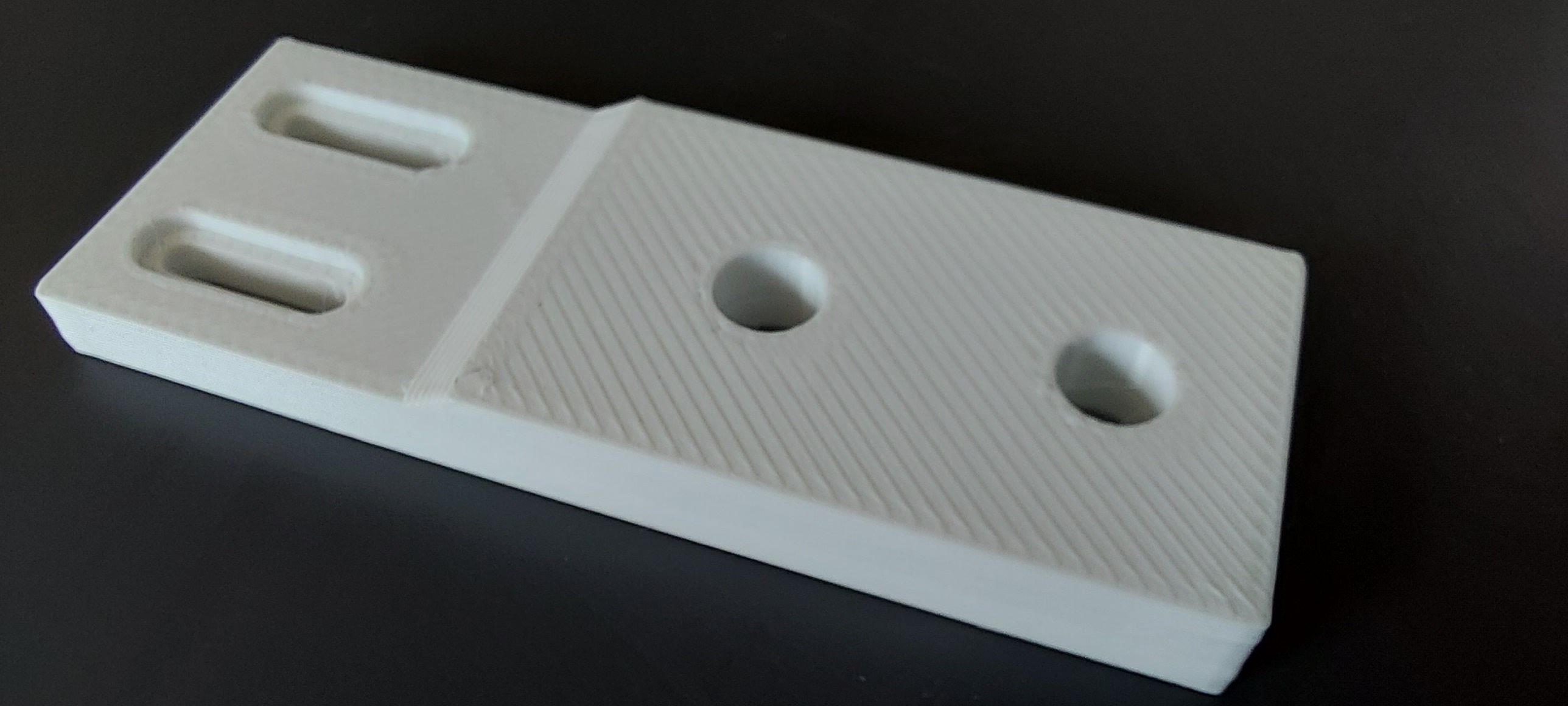
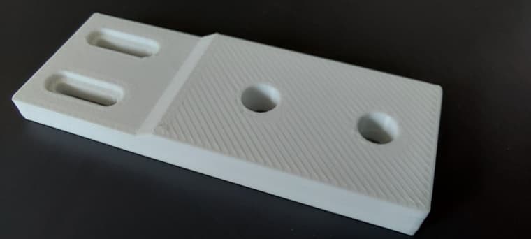
I have drawn and printed an adapter to attach a limit switch to my drawing machine.
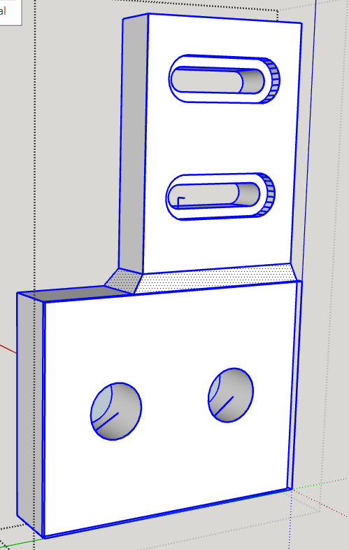
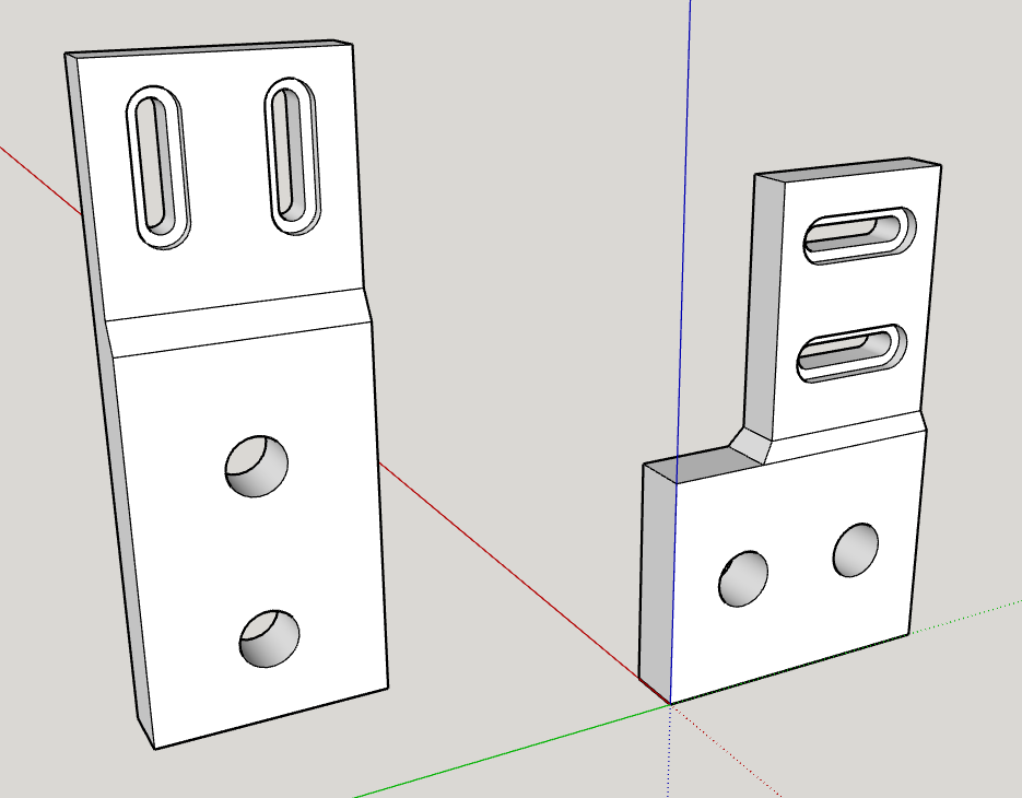
A first part (the left one in the SU file) was printed as drawn, a second, slightly modified one, was not. This should be 4mm thick at the top but only has 2; what is missing is 2mm and the countersinks around the slotted holes.
It should be noted that I did not touch the upper part in comparison to the first one, except that I rotated it by 90°.
What could be the reason for this?
Kind regards
Alohaa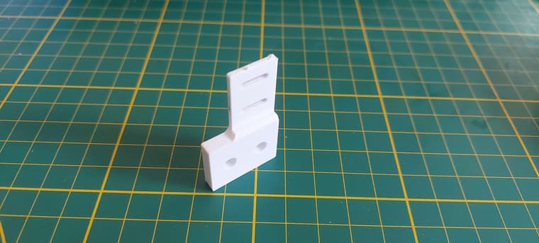
-
@Alohaa said in Part not printed as drawn:
I don't quite understand what it means that it's not solid.
In order for a group or component to be considered a solid, or manifold, every edge must be shared by exactly two faces, no fewer and no more. So no stray edges, no holes in surfaces or missing faces and no internal faces. To be properly 3D printed all faces must be correctly oriented, too. That means the white front faces must be facing the air and the blue back faces are toward the print media.
Nested groups and components will never be considered solids because they contain more than just edges and faces.
@Alohaa said in Part not printed as drawn:
What do you mean by that?
The edges and faces in the space between the object on the bottom and the one on the top are just loose geometry. Compare your model to the one I shared.
@Alohaa said in Part not printed as drawn:
What did you do exactly?
I exploded the groups inside the top level object, removed a bunch of stray geometry and other cleanup. the Solid Inspector2 extension helps to identify problems. It might fix some of it.
@Alohaa said in Part not printed as drawn:
The fact that I drew these parts in mm didn't cause any problems, or am I seeing it wrong?
It didn't in this case but you can create smoother curves and other small details if you need it.
@Alohaa said in Part not printed as drawn:
Incidentally, I recently printed a part I had drawn in metres without scaling it down because I had forgotten it was in metres, and it printed correctly, which I was amazed at and still don't understand!
The .stl file you exported has no units. It's only numbers for the sizes. So you can export with the model units as meters and import into the slicer as millimeters.
-
@Alohaa neither one of the objects is a solid in SketchUp. The L-shaped one contains two non-solid objects and loose geometry between them. There's also a lot of garbage geometry and there were some reversed faces, as well.
I've cleaned them up so they are both solids.
I'm curious. Why are you modeling these so small? We already gave you the advice to model in meters, export in meters, and import the .stl into the slicer in millimeters.
-
Thank you very much for all the work you have done with my faulty drawings!
@Dave-R said in Part not printed as drawn:
neither one of the objects is a solid in SketchUp.
I don't quite understand what it means that it's not solid.
That would mean that I am not proceeding correctly by drawing a surface and extruding it!@Dave-R said in Part not printed as drawn:
loose geometry between them
What do you mean by that?
I proceeded in such a way that I put both parts on top of each other, and on. 2 sides by creating inclined planes by drawing the individual lines to connect the parts more strongly.@Dave-R said in Part not printed as drawn:
a lot of garbage geometry and there were some reversed faces, as well.
What is garbage geometry?
I looked closely for superfluous geometry by displaying the part in the X-ray mode and found nothing superfluous.
@Dave-R said in Part not printed as drawn:
I've cleaned them up so they are both solids.
What did you do exactly?
@Dave-R said in Part not printed as drawn:
Why are you modeling these so small? We already gave you the advice to model in meters, export in meters, and import the .stl into the slicer in millimeters.
I had forgotten it again, but this is only necessary in various (although I don't know in which!) situations, or not? The fact that I drew these parts in mm didn't cause any problems, or am I seeing it wrong?
Incidentally, I recently printed a part I had drawn in metres without scaling it down because I had forgotten it was in metres, and it printed correctly, which I was amazed at and still don't understand!
-
@Alohaa said in Part not printed as drawn:
I don't quite understand what it means that it's not solid.
In order for a group or component to be considered a solid, or manifold, every edge must be shared by exactly two faces, no fewer and no more. So no stray edges, no holes in surfaces or missing faces and no internal faces. To be properly 3D printed all faces must be correctly oriented, too. That means the white front faces must be facing the air and the blue back faces are toward the print media.
Nested groups and components will never be considered solids because they contain more than just edges and faces.
@Alohaa said in Part not printed as drawn:
What do you mean by that?
The edges and faces in the space between the object on the bottom and the one on the top are just loose geometry. Compare your model to the one I shared.
@Alohaa said in Part not printed as drawn:
What did you do exactly?
I exploded the groups inside the top level object, removed a bunch of stray geometry and other cleanup. the Solid Inspector2 extension helps to identify problems. It might fix some of it.
@Alohaa said in Part not printed as drawn:
The fact that I drew these parts in mm didn't cause any problems, or am I seeing it wrong?
It didn't in this case but you can create smoother curves and other small details if you need it.
@Alohaa said in Part not printed as drawn:
Incidentally, I recently printed a part I had drawn in metres without scaling it down because I had forgotten it was in metres, and it printed correctly, which I was amazed at and still don't understand!
The .stl file you exported has no units. It's only numbers for the sizes. So you can export with the model units as meters and import into the slicer as millimeters.
-
@Dave-R Thank you!
-
 R Rich O Brien marked this topic as a question on
-
R Rich O Brien has marked this topic as solved on
Hello! It looks like you're interested in this conversation, but you don't have an account yet.
Getting fed up of having to scroll through the same posts each visit? When you register for an account, you'll always come back to exactly where you were before, and choose to be notified of new replies (either via email, or push notification). You'll also be able to save bookmarks and upvote posts to show your appreciation to other community members.
With your input, this post could be even better 💗
Register Login


Advertisement