I think the fastest way to center an object is to move it to one side of the target, move-copy it to opposite side, divide by 2 and erase the two outboard copies. of course the moves are done using midpoint inferences. try it on the attached model. in the left section, place the Belgium block on the center of the footing's long run. right hand section is desired result.
Oops, your profile's looking a bit empty! To help us tailor your experience, please fill in key details like your SketchUp version, skill level, operating system, and more. Update and save your info on your profile page today!
🚨 Skimp | 25% Off until March 30 Buy Now
P
Offline
Posts
-
Centering an object
-
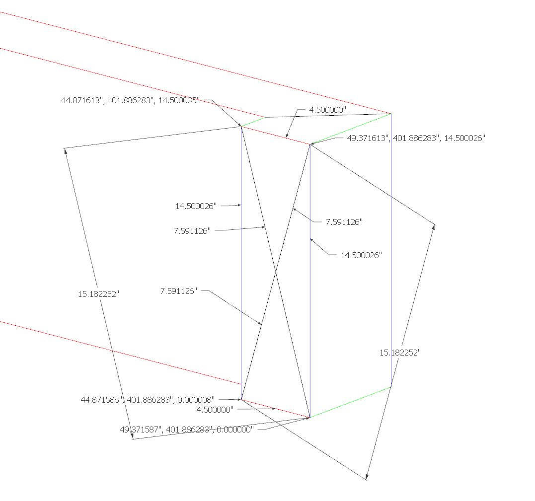
RE: UNWANTED LINES FROM FOLLOW-ME
i was relying on EDGE COLOR BY AXIS style to reveal any imperfections. I guess that's out the window now. And one would expect the diagonal and side measurements to also be off in relation to the coordinates Dave exposed.
-
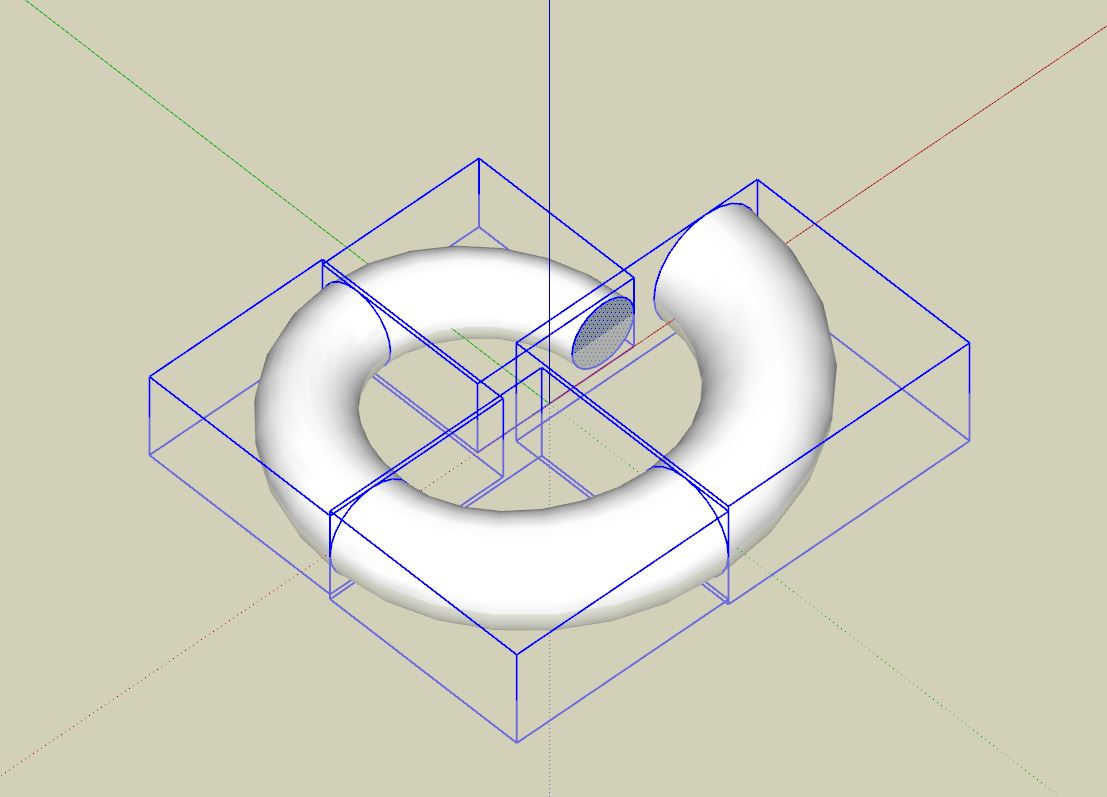
UNWANTED LINES FROM FOLLOW-ME
Why would these diagonal lines sometimes appear in straightforward extrusions?
-
RE: Groups box-stretch as components
I suspected something like that was happening. thank you Fredo6.
-
Groups box-stretch as components
if you FredoScale-box-stretch the red group, the white group also changes. there are no components in this file, so why this behavior? it only happens in one axis - apparently.
follow-up - i just tried it again - and it did not happen. but it definitely did happen time and time again earlier. if i knew how to ''video tape'' the screen action, i would post it.
-
RE: Cannot seem to move edge
wow...i have no idea how i managed to get a curve segment into my geometry! when i inspected the linework using axis by color style, i saw no black. but now i know that a curve's segment, when plumb, shows up as blue. i did a lot of finagling trying to fit separate floor levels together. and so, i must have introduced the freaky condition. nothing, however, in this file is from another program.
https://www.dropbox.com/s/dso8xz761o2a0t2/QUIN%20MODEL%20-%20sketchucation.skp?dl=0
-
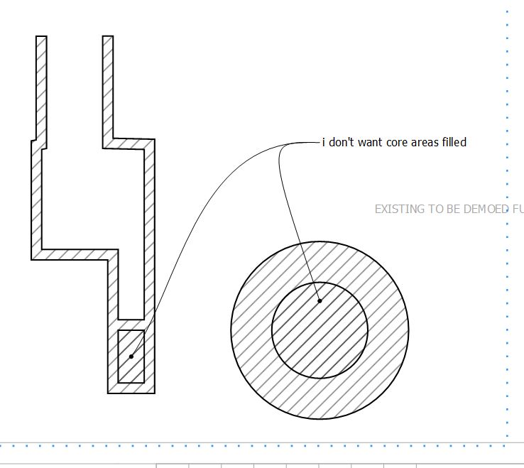
Pattern Fill Boundaries
Can pattern fill be controlled to obey certain boundaries?
-
RE: Curviloft default settings
From what i can see, there is no such thing as default parameters for Fredo6:Bezier Spline - correct?
-
RE: Extension warehouse [skp 2019]
I found the solution. Sign in with the google sign-in method vs. the email address method. The email address method is the 'default' method since the field has the blinking cursor in it.
-
Extension warehouse [skp 2019]
I installed SKP 2019 into primary computer and opened the extensions warehouse, signed in, and saw the full list of my extensions. I successfully installed same. However, on another visit to said warehouse when i installed 2019 into a secondary computer - all my extensions were missing except for the few "built-in" ones (trimble connect, advanced camera tools, dynamic components and sandbox tools). What gives? Not even visible thru primary computer.
-
RE: Keyboard shortcuts
Never mind. I was using the right-click toolbar area > customize > options tab > keyboard button instead of edit menu > preferences > shortcuts.
-
Keyboard shortcuts
I assigned the K key as a shortcut for the label tool in LayOut. Just a simple press of the K key - not in combination with shift or ctrl. But now I can't figure out how I did it. The interface is not as good as sketchup's.
-
RE: Text Label Tool Behavior
OK. But I wonder why the text tool correctly reports the revised edge length if i stretch the cylinder using fredo scale box stretching. After all, it has been re-scaled since the context menu un-grays the option to reset same.
-
Text Label Tool Behavior
When you attach a text label to an edge, it should display its length. But it is way off on one of the objects here. What am I not understanding?
-
RE: Curviloft default settings
That's OK. I will just continue doing it in 4 pieces, then 'welding' them together.