sketchucation logo sketchucation
    • Login
    1. Home
    2. pipingguy
    3. Posts
    Oops, your profile's looking a bit empty! To help us tailor your experience, please fill in key details like your SketchUp version, skill level, operating system, and more. Update and save your info on your profile page today!
    โš ๏ธ Important | Libfredo 15.6b introduces important bugfixes for Fredo's Extensions Update
    P
    Offline
    • Profile
    • Following 0
    • Followers 0
    • Topics 124
    • Posts 398
    • Groups 1

    Posts

    Recent Best Controversial
    • RE: Curviloft default settings

      OK.....I updated my Fredo files. However, I am still unable to preserve the parameter 'junction by orthogonal elliptical curves' as a user-defined default. I am not really seeing anything in the parameters dialogue box that would be applicable. See attached images.


      default parameters 1 of 3.JPG


      default parameters 2 of 3.JPG


      default parameters 3 of 3.JPG


      check fredo for update.JPG

      posted in Plugins
      P
      pipingguy
    • 'stress' lines appear in AutoCAD

      Take a look at the attachment. Autodesk forum suggests I build models in their environment since "Trimble and Autodesk are not playing well together". Note - if i export out of sketchup as 2D graphic, the stress lines do not occur - but I need to work in 3D 90% of the time.


      stress lines 1-4-19.pdf

      posted in SketchUp Discussions sketchup
      P
      pipingguy
    • RE: LO 2018 - exporting to .dwg becomes image file

      OK - Thanks.

      DISCOVERED: If I leave LO's VP's as raster, the export process generates a .dwg file PLUS a folder containing the png image files. When the .dwg file is opened with AutoCAD, it xrefs the images - but you can freeze the images layer to have a wireframe visual style, if desired.

      posted in LayOut Discussions
      P
      pipingguy
    • LO 2018 - exporting to .dwg becomes image file

      When I export a LayOut file to a .dwg file extension choice, it ends up as a .png file. Actually, a separate .png file for each LO viewport is generated.

      posted in LayOut Discussions layout
      P
      pipingguy
    • RE: Curviloft default settings

      I wish it would retain settings as you describe. But it always reverts back to 'smooth junction by a single cubic bezier curve' every time I activate the tool within the same session. Could outdated script be the issue? see attached pdf.


      update.JPG


      revert.pdf

      posted in Plugins
      P
      pipingguy
    • RE: Curviloft default settings

      In the "Default Parameters: Curviloft" thing being suggested, I just tried unchecking all boxes associated with quads > saved changes > re-launched skp - but still getting same old softened edge results.

      posted in Plugins
      P
      pipingguy
    • Curviloft default settings

      When using "loft junctions between surfaces based on spline curves", can the various choices in each of the tool palette's panels be set as user-defined defaults? For example, 95% of the time I use 'junction by orthogonal elliptical curves' in the Spline Method panel. Also - is there a way to force the generated geometry's edges to follow a user's pre-defined degree of softness? Just trying to save some click time.

      posted in Plugins
      P
      pipingguy
    • LayOut VP refresh tip

      If you change a camera position in a model's scene, and then update model reference in the associated LO file, you would expect the viewport linked to that scene to automatically update. However, it rarely seems to work for me. ๐Ÿ˜ž But then I tried re-check-marking the scene in the viewport's context menu and got success. ๐Ÿ˜„

      posted in LayOut Discussions layout
      P
      pipingguy
    • Nudge stuff in LayOut el-rapido

      I never knew you could ''hyper-nudge'' selected objects by holding down the the shift key while using the arrow keys. Is this an improvement in 2018, or has it been around for a while? ๐Ÿ˜ฎ

      posted in LayOut Discussions layout
      P
      pipingguy
    • RE: Hidden lines not visible in Layout

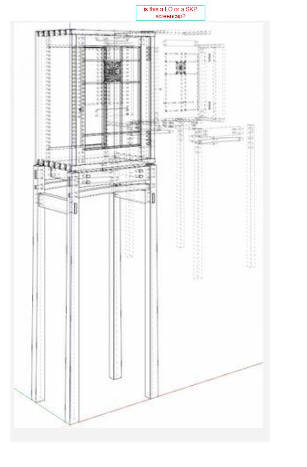
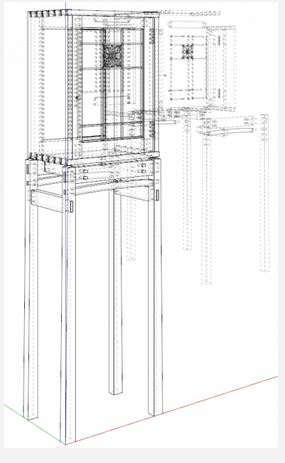
      OK Dave....now I understand what's going on. At first, I thought the foreground object had a style that shows both solid and dashed lines, and the other one had a style with dashed lines only - although I am not aware of any such style. But your opaque screen is what gives the effect to the latter - not a separate style. This post piqued my interest because it just so happens I had to generate a CD for a steel angle iron frame a few days ago. But I became frustrated at not being able to find a style/render combo to clearly display dashed line back edges. Raster/back edges works, but gives a fuzzy result. And as was mentioned in the post, dashed lines need to be manually traced onto the canvas with LO's line tool. Not something I care to do since several modifications to the object's design often take place which requires time-consuming manual re-tracing updates in LO.

      posted in LayOut Discussions
      P
      pipingguy
    • RE: Hidden lines not visible in Layout

      I agree. So how are two different styles being displayed? What am I not comprehending?

      posted in LayOut Discussions
      P
      pipingguy
    • RE: Hidden lines not visible in Layout

      see below.........


      two different styles being simultaneously displayed in one model.JPG

      posted in LayOut Discussions
      P
      pipingguy
    • RE: Hidden lines not visible in Layout

      I'm a little confused. How can two different styles exist on one skp screen? Or is it a LO screencap with two overlapping VP's with each having different styles? The axis lines makes me think the former.


      two different styles being simultaneously displayed in one model.JPG

      posted in LayOut Discussions
      P
      pipingguy
    • RE: Zoom speed in LayOut

      Try using Logitech's M705 mouse. The scroll wheel click action can be disabled by an adjacent button to speed zoom action. It still won't match AutoCAD's zoom speed - at least not in its wireframe visual style.

      posted in LayOut Discussions
      P
      pipingguy
    • RE: Half-round rope molding

      i tried it without benefit of a left hand plus a right hand rope. close enough. a little sanding and touch-up paint and no one will notice unless they are a basketball player. ๐Ÿ˜„
      some funny stuff in this link........

      http://forums.finehomebuilding.com/breaktime/construction-techniques/rope-molding-outside-corner-miter-tips


      rope molding quandry rev-1.skp

      posted in Woodworking
      P
      pipingguy
    • RE: Half-round rope molding

      how do you know so darned much sir?

      posted in Woodworking
      P
      pipingguy
    • RE: HYPHEN

      wonderful

      posted in LayOut Discussions
      P
      pipingguy
    • Half-round rope molding

      before i physically mutilate the pre-finished poplar subject item that's supposed to adorn a cabinet-top crowne molding with an outside corner, i tried doing it with skp....but with no luck. maybe if the two workpieces had opposite hands, but they don't.


      rope molding quandry.skp

      posted in Woodworking
      P
      pipingguy
    • RE: HYPHEN

      Now I remember why I switched to Arial - it's because certain subsequent Tahoma characters, such as RA and TT, touch each other. ๐Ÿ˜ฎ So when I convert the 3D text component into a group, those faces get left behind. I wish Trimble would separate the letters or allow 3D text to form a group vs. component.

      posted in LayOut Discussions
      P
      pipingguy
    • RE: Overlapping dimension extension lines in LO

      For any AutoCAD users out there....I found a LISP routine that identifies these little buggers.

      posted in LayOut Discussions
      P
      pipingguy
    • 1 / 1