sketchucation logo sketchucation
    • Login
    1. Home
    2. mac1
    3. Posts
    Oops, your profile's looking a bit empty! To help us tailor your experience, please fill in key details like your SketchUp version, skill level, operating system, and more. Update and save your info on your profile page today!
    ⚠️ Important | Libfredo 15.6b introduces important bugfixes for Fredo's Extensions Update
    M
    Offline
    • Profile
    • Following 0
    • Followers 0
    • Topics 7
    • Posts 872
    • Groups 1

    Posts

    Recent Best Controversial
    • RE: How to determine the lenght of an arc

      @brandy20 said:

      I'd like to draw an arc of a predetermined lenght. Is there a simple way or a plugin to get it quickly without doing math every time?

      Thanks,

      Luca

      I doubt it since there are an infinite number of arcs you can draw at a predetermined length. Remember you need both the angle and radius. ❓

      posted in SketchUp Discussions
      M
      mac1
    • RE: Transfer files to new computer?

      One other though. Some of the OS's have a transferr wizard that step your through the process. I was assuming just a disk chage 😳

      posted in Hardware
      M
      mac1
    • RE: Transfer files to new computer?

      In the past I replaced a 300GB HD with a 600GB drive and will start the process of replacing my present drive with a solid state drive tomorrow. You can make a image( aka clone) of the existing drive using your USB port , replace old with new and turn on and it will look exactly like your old drive including the operating system. On the first go around I bought a usb inclosure. ( Not expensive and they even have the conversion electronics to make the USB interface.) I think it was about $20-$30. For this second case Crucial(sic??) sells the 2.5 to 3.5 rail conversion, clone software and the cable for the usb to drive along with the drive. Since it is solid state they us the USB power. For mechanical HD power supply was part of my enclosure.
      The first time I used Acronis True Image software.
      I think it would be best for you to talk to a local store like Micro Center and then based on what you really want to do they can suggest an approach simple to more complex. A more global search on the net may help also especially like some of the journals and even Tigger Direct and New Egg.
      If you are no making a clone spend some time early to clean up and organize our files it will make the effort much simpler. I just completed today some major changes and don't forget about the drivers for the varions things like printer, internet connect display,sound. etc. It will help if you have the install disks.
      Good Luck

      posted in Hardware
      M
      mac1
    • RE: Strange behaviour of SU when molding a door

      brandy20 thanks for the clarification.
      Sorry for getting back late. Struggling with computer and trying to deleted old w98 set as dual boot with my XP. Would you believe. πŸ‘Ž
      I got the small dimensions from the original post showing they were scaled by x100 but that is not the real issue.
      Is it correct to assume when you route you do like a dry fit of the two mating rail and stile so you have something to ref from. Doing separately was my concern.
      I guess I mislead everyone on the follow me tool. Was just trying to show one can get down to relative small size. It has served many people well.

      BTW: The older I get the more I realize it is dumber, dumber and dumber when I see all the great talent around. It's like the older one gets the better you were. That is just a fact of life =>technology marches on.

      posted in SketchUp Discussions
      M
      mac1
    • RE: Plugins that use CPU when idle?

      Go here http://technet.microsoft.com/en-us/sysinternals. They have some utilities that nay help like proc. monitor ,virtual memory map stc. You could try and open task manager, and shut down all processes expect for those required for the system. ( When you restart they will restart so don't do that.) Then watch the performance monitor screen( control panel , admin tools , performance not the task manager process monitor) You can check happenings thru out by adding various monitor points. You could even contact Mark at System Internals and see if he would make a TS suggestion.
      Just some thoughts.
      BTW the 1/2, 1/2, 1/2 is only a binary search if the probability of occurrence are equal. If they are not equal then the groupings are adjusted accordingly to make the guess entropy equal as possible

      posted in Plugins
      M
      mac1
    • RE: Strange behaviour of SU when molding a door

      Jeff sorry but not quite.
      I was coming off the fact I got the message from the OP he was going to build the components as shown and yes I know the scale shown in the OP is not reasonable ,but I consider that immaterial to the safety issue. Those components show a short stub on the component that would have to be milled some way either by a bearing guided bit or a table + fence or bearing bit + guide post or ❓ ❓ ❓ IMHO that can become dangerous very quickly if by router. That was what I have been screaming about. Hope the OP can enlighten me and I will obviously learn some thing. Probably I am stupid 😳

      posted in SketchUp Discussions
      M
      mac1
    • RE: Plugins that use CPU when idle?

      Intersting. You can do what is called a maximum entropy search and find the problem relative quickly. Just keep splitting the # of plugins in 1/2 each time. If the first 1/2 does not fail then it must be in the 1/2 you did not load etc. If you have more than one causing the problem then it gets more dicey

      posted in Plugins
      M
      mac1
    • RE: Strange behaviour of SU when molding a door

      @unknownuser said:

      @mac1 said:

      For general interest here is the widow to scale using the follow me tool and better modelling practice.
      Started extrusion further from bottom corner.
      Use 2nd order Bezier to form better tangents than the arc tool.

      mac, i think you're missing a key element of this thread.. the corners are rounded.. not square as in your drawings..
      i think it's been stated a few times in this thread by a few different people that follow-me is ok for angular intersections.. the problems arise when the path is an arc/curve

      [attachment=0:1xvr54f4]<!-- ia0 -->sporty_ello_diff.jpg<!-- ia0 -->[/attachment:1xvr54f4]

      Look at my above post=> I model as I build. I have stated more than once the OP has indicated to build as separate components and that is dangerous or at least I think so. I will not post anything I think can lead to a safety issue. Maybe you can build and cut the profiles with a router but I cannot not. 😠

      posted in SketchUp Discussions
      M
      mac1
    • RE: Strange behaviour of SU when molding a door

      @tig said:

      Mac1, isn't that all 100x too small ?? Look at the dimensions no door is 3mm wide ?

      Look at the OP he shows it scaled by 100X. I know look at why I questioned his scale above.

      posted in SketchUp Discussions
      M
      mac1
    • RE: Help with lofting and intersecting

      Several comments for you to think about;

      1. Su uses layers only for visibility control and not geometry isolation. That is done by the use of components and groups. So for the shelf if I double click and select a line it should show as being on layer 0. So in the layer dialog delete that layer and select move to default layer. Then in the entity info assign that group to layer shelf after you remake it. Suggest you do the same with the shell;
      2. The shel thickness varies, to make it all the same delete the top surface , delete the edges and then use the push pull to make it .0625. While you are at it change units to decimal and deselect all snaps. In some cases you have line segs of 10.7 mils and others of 102.2 mils in what are straight lines . The one line seg has 126 edges. Redo some of those and make consistent;
      3. For the shell consider using its symmetry and model only 1/2 and and mirror of the other part. Need to clean up the curves they are not very uniform and "bumpy";
      4. Look at TIGs extrude plugin set. This may be better for your use and the number of vertices will not be so large. Here is my quick cut at outer shell
        shell concept.jpg
      posted in Organic Modelling
      M
      mac1
    • RE: Strange behaviour of SU when molding a door

      spotello window to scale with follow me tool.jpgNot really I have better things to do.
      For general interest here is the widow to scale using the follow me tool and better modelling practice.
      Started extrusion further from bottom corner.
      Use 2nd order Bezier to form better tangents than the arc tool.

      posted in SketchUp Discussions
      M
      mac1
    • RE: Strange behaviour of SU when molding a door

      Per request http://sketchup.google.com/3dwarehouse/details?mid=97f6c7269341fe93483a6eca16661274 below the OP scale the model starts to have SU size issues.
      Barndy20 please reconsider trying to mould the component approach it is dangerous

      posted in SketchUp Discussions
      M
      mac1
    • RE: Strange behaviour of SU when molding a door

      We have to agree to disagree. Follow me has been around for some time and as with many things they get over taken by progress. To call it junk I think does a disservice to the creator. If the model is made carefully it works fine. As posted many times you must scale up by a relative large number for that to happen. More than the OP.
      I have posted many times there is no tangent in SU by the mathematical definition ( unless you think a straight line is appropriate for consideration.). The designers have come up with an approach and if you don't like that why use it?
      TIG's tools are very nice because they are adaptive in the sense a relative fixed geo is not required.

      posted in SketchUp Discussions
      M
      mac1
    • RE: Strange behaviour of SU when molding a door

      Brandy20
      Another comment. Make the model like one will typically build the door. Assemble the rail and stiles first and then do the moulding cut just like you would with a real door. It seems to me cutting the individual rail and stile components would be difficult and dangerous if possible at all. 😍 If you do it this way the follow tool will work very nicely.

      posted in SketchUp Discussions
      M
      mac1
    • RE: Strange behaviour of SU when molding a door

      @brandy20 said:

      First, thanks to everybody for taking the time to get inside the problem and answer me.

      I'll try to answer you in order of appearance πŸ˜‰

      Charlie: I only have the pro for v7. My v8 is free so I don't have Solid Tools. Anyway I took a look to your file and the path you used for the molding is not the same I used. Look at the corners, I have a curve and you just used two segments. Try with my curve and I suppose you will have my results, since ST are an evoluted way of telling SketchUp to intersect geometries. The problem lies in THAT curve because SU tries to perform that curve also on the internal side of the molding but has to create extra geometry that is partially compensated by very short segment when you scale up the model by 1000 times.

      Mac1: I think you really got the point of what I mean. SU creates sequential vectors following the path, that's why I'm experiencing the problem. I didn't try to resize with the tape tool, I'll do it soon. The measures are 568mm by 328mm. Where did you find .568? It's not a micro door... πŸ˜„

      @unknownuser said:

      I used your first scene and must have scaled by 1/1000 vs 1/100. 😳 Save and reopen works ok. Do not think you need to eliminate the arc. Under stand even though your model is 5.68 mm tall when you do the follow me there are areas where that dimension is much smaller. I am not exactly clear on your work flow and the associated problems. Am I correct in the assumption for some case you were doing each component on a stand alone basis? You want to do the follow me around the whole perimeter at once so the boundary values are correct to let the follow tool do its thing or as Dave indicted above you can establish the correct boundary values by extension. Try by scaling up by larger value then back down but boundary values must still be maintained if you do a component at a time.
      The issue of scale up , scale down ok but close/open is not I have no answer for. Pure guess it could be a graphics issue. Do not use any type of length snapping ❓
      @unknownuser said:

      Eliminating the arc and drawing two segments at the corners would be an alternative but I wanted to draw that door as it was routed in the shop. And then, another question is still open: why I can accomplish the task I want, scaling up the model, doing the Follow Me and scaling back with no problems BUT when I save the model or the components SU looses some faces? If SU can't handle very short segments it should start loosing faces just after the scale down. ❓

      Should I think of it as a limit of SketchUp and change the molding path?

      Luca

      posted in SketchUp Discussions
      M
      mac1
    • RE: Strange behaviour of SU when molding a door

      %(#BF00FF)[<Postby brandy20 on Sun Oct 30, 2011 6:17 pm
      Hi Dave,

      this is exactly what I did and the match is fine on the external path, but not internally. I also tried to run the follow me on the complete loop and paste it in place separately in every component but the result is the same.>]

      Luca

      Brandy FYI
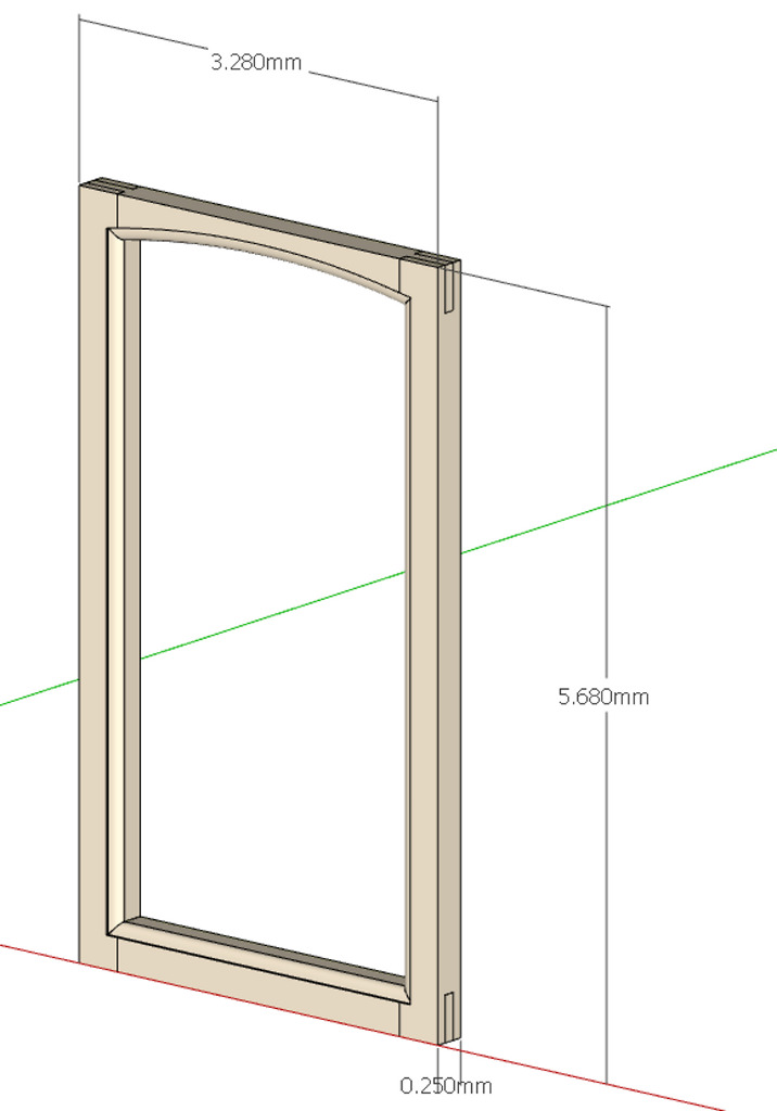
      The way the follow me tool works is it's projecting along sequential vectors define by the path you select. At the very first step, if the surface is not perpendicular, then the surface is basically reduced in size by the cosine of the angular error. To get the size you want make sure this criteria is followed=> it will be in error all the way around however.
      Because of this projection and my assumption were you were trying to do the extrusion on each component separately (not with standing your above comment) you are not giving the program enough info to allow for correct corner formation and thus the errors. I exploded your 1000 scale model and did the loop approach and it worked just fine. I then scaled down by 1/100 and then 1/10 with the first step ok but the second was not very good. I then used the tape tool to resize to your .568 mm height and that worked fine. Scaling up more than back down ( based on previous postings ) will probably work but did not try that.
      Why so small to start with?? ~ 1mm is the break point 😍
      Just some thoughts

      posted in SketchUp Discussions
      M
      mac1
    • RE: Big problem to build my Hull !

      boatHull_A..png
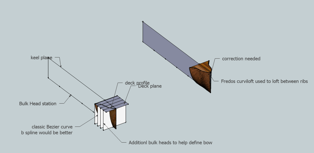
Here is a concept that may work for you. Probably have two many points on the bezier splines. You choice on how you want the contour to look.
      Maybe you can get Fredo to include a real b spline curve in his tool

      posted in Newbie Forum
      M
      mac1
    • RE: Big problem to build my Hull !

      Have a concept approach for you but power failed Wed AM. Hope back NLT Frir PM.
      You can use the approach of a plane thru the keel, a deck plane and the planes thru each station ( prependicular to keel plane)and used Freeod's Bezier tool to draw the profiles and then his curviloft for the skin. If you read the PDF manual Defltship has publsed this is some what along that approach except they connect points on bulkheads ( think they call them chines?) longitudinally. This is where your personilaization comes in. ❓

      posted in Newbie Forum
      M
      mac1
    • RE: Big problem to build my Hull !

      Another consideration
      Strip your present model of the propriety items and post. Looking for just the bulk heads at some selected stations. I think one can smooth out the hull where you are having the problem and probably does not need defltship. I looked a little for a b spline program but did not find one , but think Fredo's BZ spline programs may get you there. It is not most desirable but maybe good enough.
      I don't want to spend time without any idea of the profile you want thought.
      The idea would be to show you the work flow and let you do the actual design.
      Just some thoughts

      posted in Newbie Forum
      M
      mac1
    • RE: Help with creating faces on an imported CAD file...

      lines, circles etc.
      To do that open up the layers drop down, select the three below layer 0 and at top select the minus sign. You will then be given three options and elect the one to move contents to default layer. If yo now go back and double click one of those components( group) to get in edit mode, then select say a line and then look at the entity drop down you will see it is on layer0. You can then go back to the layer drop down and make a new layer, select that group ( don't double click ) you can re-assign that group to that layer but its internal geometry will still be on layer zero where you want it. I would recommend you use components but not necessary. You can recreate the other two layers and gives you the capability of hiding geo while you model and the others not interacting with each other.
      BTW when you use the staryline tool make sure you are in the context of the group( double click first). Also to correct some errors ( like you may have a case where two lines do not quite meet at the vertex in maybe easier to use the move tool to grab the end point and move to the other one. However that can distort geometry so I will often delete one of those lines and move the others end point to the terminus connect vertex of the deleted line. The use of the triangle approach is useful soem times but you should not need it much.
      Also if you go to windows preference, extensions, utilities and make sure extensions are enabled then on the tools tool bar fly out it will have a create face option under utilities. That sometimes is helpful because it will say why a face was not created. It is not very robust however.
      Hope this helps. You will learn some of these moves as you model more. Its a learning experience
      SU implemented an auto intersect in I think was 7 so crossing planar lines in the same context will do what you describe. It is normal. If they are in two different components they will not do that.
      good Luck

      posted in Newbie Forum
      M
      mac1
    • 1 / 1