sketchucation logo sketchucation
    • Login
    1. Home
    2. mac1
    3. Posts
    ℹ️ Licensed Extensions | FredoBatch, ElevationProfile, FredoSketch, LayOps, MatSim and Pic2Shape will require license from Sept 1st More Info
    M
    Offline
    • Profile
    • Following 0
    • Followers 0
    • Topics 7
    • Posts 872
    • Groups 1

    Posts

    Recent Best Controversial
    • RE: Help with soap skin bubble plugin on handcycle model

      Gallen
      Attached is concept for you;

      1. Your op model is very non-symmetrical, selected the planar face you have;
      2. Used Chris Fullmers shape bender to create what I guessed you may want;
      3. Made a mirror copy so some symmetry is now present;
      4. Use Freedos curivloft to make faces 😑

      Handcycle mockA.skp

      posted in Newbie Forum
      M
      mac1
    • RE: Dividing complex curved surface?

      FenchurchXone: attached is a different view for your info. I used the model you posted just above, Curivzard ( One of Fredos tools) to simplify and smooth its contours, poly line segmenter to set equal vertices on the edges, TIG's extrude tool set to the create the faces. This was used as a proof of concept and will have to be re-done for a final drawing. I under stand you are not expecting fidelity ,but here is some info I obtained that maybe useful to you at some point. http://www.20fenchurchstreet.co.uk/schedule-areas.html
      Levels are 34 ( Window mullions stop here) and then 3 levels at the top for the sky garden; total height is 522 ft to top of roof; levels are in this link; as shown two opposite sides are concave and other two are convex.
      IMHO use of Soap, Skin and bubble is not the best plugin for you.

      posted in Newbie Forum
      M
      mac1
    • RE: Dividing complex curved surface?

      Xone: attached is a different view for your info. I used the model you posted just above; Curivzard ( One of Fredos tools) to simplify and smooth its contours; poly line segmenter to set equal vertices on the edges; TIG's extrude tool set to the create the faces.
      This was used as a proof of concept and will have to be re-done for a final drawing. I under stand you are not expecting fidelity ,but here is some info I obtained that maybe useful to you at some point.
      Levels are 34 ( Window mullions stop here) and then 3 levels at the top for the sky garden; total height is 522 ft to top of roof; levels are in following link; as shown two opposite sides are concave and other two are convex.[attachment=0:14wg7bp6]<!-- ia0 -->shape (1).skp<!-- ia0 -->[/attachment:14wg7bp6]
      IMHO use of Soap, Skin and bubble is not the best plugin for you.
      http://www.20fenchurchstreet.co.uk/schedule-areas.html

      posted in Newbie Forum
      M
      mac1
    • RE: Dividing complex curved surface?

      schorice31.jpgThe walkie scorchie=> sun reflection melted a jag. πŸ˜„
      Is it possible to get you to post skp file?
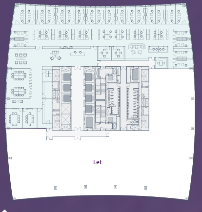
      The PR brochures shows cross sections of floors 4, 31, and 34 and seems to show different profile than your model but that just may be a image view point??
      Here is #31

      posted in Newbie Forum
      M
      mac1
    • RE: Coordinate System Issue

      @djohnson.nz said:

      I often use Sketchup to model topographical surveys.
      I use the query tool to show the coordinates of various objects within the model.
      .....
      Can anyone give me a work around for this or would it be possible to have a "query tool"
      that would allow a constant to be applied to x, y, and z coordinates so when used it would show the coordinates as they were in the original survey.

      Ideally it would be great to be able to set up an independent origin that allowed me to query and export the data at the same coordinates as the original survey. Even if the model was geo-referenced to its Google Earth location.

      Thanks, David.

      Not my wheel house but their are number of different datum's used. The shape of the earth is estimated by curve fit to data using spherical harmonics with the bottom line the same point will have different locations reported even though the point has not actually moved. Costal areas even carry that further and may actually report different elevations for example the Ordnance Survey used in England. My sense is you will not find making correction as simple as adding a constantt to the data since the cruve fit is transcendental in nature.
      See http://en.wikipedia.org/wiki/North_American_Datum
      https://www.e-education.psu.edu/natureofgeoinfo/c2_p16.html#comment-6996
      http://www.uwgb.edu/dutchs/UsefulData/UTMFormulas.htm

      posted in Plugins
      M
      mac1
    • RE: I love this website, I hate this webpage.

      For me I think this site is ok and not an outlier vs other sites I visit.
      FYI: There are 82 web sites with content on this current page and 7 services with content block by my tracking protection. It is showing 0.9 msec paint time, frame rate of 56 /sec, 135 MB and low CPU usage. The speed of loading can be influenced by the quality of the total link , I have seen packets going to Europe and back ( don't remember if it was this site) but can be strongly influenced by happenings owners have no control over.
      You need to get use to slower speed as a result of the recent hacking going on as more protection will probably be implemented.

      posted in Ideas Box & Board Issues
      M
      mac1
    • RE: Make edges turn into a surface?

      LARV:
      Off topic but info for you.
      Since you are on windows this assumes you are using Internet explorer. Look at top right of your screen there maybe safety, tools you can click that shows some of the protections; #2 At the top in the navigation bar you may see a circle with a line thru it. Clicking on that will show what is blocked; #3 At the top left under tools select compatibility view then open the internet explore privacy statement and will step you thru all the various issues. I have a major issue with tracking sites some videos will not run and I have to unblock all content. Blocking adds is only one issue. I have had cases where there maybe a few to tens of tracking sites blocked. Althought this site is much better than the other sketchup help site.
      The bottom line is you have to protect and educate your self the best you can and not rely on other folks.

      posted in SketchUp Discussions
      M
      mac1
    • RE: [Proto] Generating Terrain from a Cloud of Points

      @fredo6 said:

      @mac1 said:

      By the way what is exactly Voronoi filtering (The Meshlab demos refers to Poisson disk)?

      Fredo

      I can not give exact definition but is my understanding is the output is more of an interpolation of the input data rather than a estimation like some of the other filters. The voronoi filter is included in meash lab program and this link is rather interesting and covers how to convert the veronoi shell to a solid suitable for 3 printing http://meshlabstuff.blogspot.com/2009/04/creating-voronoi-sphere-2.html

      posted in Plugins
      M
      mac1
    • RE: [Proto] Generating Terrain from a Cloud of Points

      @fredo6 said:

      @roland joseph said:

      I am saying for me at least generating a terrain with cloud point is not very exciting. It would be selfish to say I would rather a talent like you work on other things. πŸ˜„

      I think that generation of terrain is an essential feature for Sketchup, not to say that making organic shapes from control points can be useful too.
      Actually, this is not something simple to develop in Ruby, because of the lack of efficient algorithms and the variety of topological situation. So nothing straightforward in this plugin project.

      Fredo

      Not by wheel house but using posted point cloud data must be predicated on high confidence the data you are using is "good". Some of the data you have used looks good visually but appears to include several data sets and some of the vertex normals questionable.You cannot tell that by using SU to just look at the data. "....You probably do not need shading so using a mesh built using Voronoi Filtering may be more useful but it needs a very clean data set to work with."
      Ref http://meshlabstuff.blogspot.com/2009/09/meshing-point-clouds.html. I am guessing contacting them they may very well have good test case for you?

      posted in Plugins
      M
      mac1
    • RE: Mini woodworking challenge

      Sloppy or too tight joints can result in reduced strength. Bond line thickness should be controlled for max. strength. I use bond wires or beads to make that happen if I am concerned about getting max strength from joint. Ref https://www.dropbox.com/s/sg6rmadbzr4ahxb/fpl_gtr190.pdf?dl=0

      posted in Woodworking
      M
      mac1
    • RE: Mini woodworking challenge

      [quote="baz"]In case you havent looked at the model, here is my assembly sequence, followed by Daves suggestion if I understood his description.
      As Sib says trying to fit too many doms at one time is a PITA, hence my current solution.
      I do mess with the doms on occasion, but only when my joinery has been sloppy, in this case I am relying on the doms to line everything up perfectly. These are a for a commercial installation, a bar in a big hotel, so I am going for maximum strength.[quote]
      I have not open your model=> have not installed SU 2015 yet.
      If item is long small error end up in large errors.
      IMHO you need to assume doms cannot be installed " perfectly". I have a series of different length witness gauges I use with connectors from Veritas so do not have to use folding ruller to try and check square. Would use epoxy for strength and gap filling so sloppy doms would not be a problem and would have longer assembly time. Epoxy not repairable however:

      posted in Woodworking
      M
      mac1
    • RE: Mini woodworking challenge

      It certainty looks like you can glue up in steps. Couple of tricks I have used over the years:

      1. I install glue blocks for clamping with brown paper bag material at inter face. You can get reasonable clamping pressure and they are easily knock off when you are done. Down side is glue can act as pore filler and give problem in finish. Waxilte can be used to help;
      2. I like to use hide glue because of its reparability and you can add a small amout of terp which decreases the vapor pressure and makes the set up time longer. I am in Colorado and in summer low humidity that helps a lots. If you check web site of your glue vendor they may have info, Fine Wood Working had an article some time ago.
        BTW dry fitting helps ( glue up sequence) with speed of assembly with all clamps etc laid out.
        The design is simple so #1 probably not required
      posted in Woodworking
      M
      mac1
    • RE: Solar north plugin (2015)

      I just recently had problem and is related to the Windows browsing feature I had set. It was blocking some content.
      At top in the navigation bar check to see if you have the circle with bar through it. If so click that and select enable all content or disable any blocking showing.
      If that helps you may want to select tools and the compatibility view settings, click the learn more link . There is a good windows write up explaining all the various interactions

      posted in Plugins
      M
      mac1
    • RE: Spiral help please

      @kathryng said:

      Oh I got all of that. It was not the array that was the problem, it was that when I copied the array and moved it up on the blue axis it did not line up? Guess I'll try it again...

      Reason you have the unconnected points the line you are dealing with is really a diagonal of a rectangle and needs to be longer than the segment of the circle and the angle is established by how much you want the lead angle.
      To get the correct angle and line length just extrude the top face of the circle for example 1 foot, draw a diagonal line from one circle end point to the next one on top the that circle, that will give the line length and the angle. The you can do the radial copy and they will match, then do a right to left select of those lines and use the array copy to copy to height you want or you could delete the lines you don't want and then copy up=> up to you.
      BTW the 1 foot is probably bigger than you want since you are moving up 1 ft for each 15 degs. of rotation assuming you are using the default 24 seg. circle. That is your design decision. Moving up the end point will also work but you need to be very careful to use the inference engine or you can easily be in error by a small number

      posted in Newbie Forum
      M
      mac1
    • RE: Printing/Plotting

      Added info:
      The fractional conversion precision you have set in SU will affect what SU shows in say the entity info dialog. Take your 21 9/16, enter as decimal 21.5625 and set precision at 1/16, entity info reports 21 9/16, but set to say 1/2 and it will report with a different number with tilda showing only approximation. That precision basically controls the size of the denominator so you no not get cases where you have ie 100 /500 which would be use less to user. ( reason you can only set up to 1/64) If you see a case with the tilda you want to increase precision. For what you are trying to do I would never use that format
      I am more convinced part of the issue maybe you are violating the interface to the printer, the manual gives specs . BTW the maintenance manual is on thier site. I would have both near by! The print heads are basically same as in many small format printers. It converts the post script to raster via the included RPI I mention above and prints as raster so you need to make sure you have the correct inter face. When you feed it raster and the printer expects vector ?? Note there are also windows and auto CAD drivers what are you using?

      posted in Woodworking
      M
      mac1
    • RE: Printing/Plotting

      @lockha said:

      To Mac1- I did find the manual online, but didn't see anything in it that would help us.

      < Section 11 , if my memory is correct, shows calibration and other sections show paper aligment>

      I'm starting to understand where you're coming from in the decimal/fractional conversation- clearly there is a difference between 1.2 and 1 3/16, but that's not the inaccuracy i have a problem with. The issue is that something on a printed drawing measures 22 3/4 when it should measure 21 9/16 (or 22.75 vs 21.5625)

      < I did not expect that would be closed form answer to you problem. I usually try to eliminate as many unknows as possible if it is easy to do. Su native dimension is inches so it needs to convert. It knows your monitor parameters via EDID( Extended display identification data) so knows its native resolution to allow calculation of pixel extent of line and same for printer DPI>

      As to the HGH accuracy, you refer to a setup box- I've looked at Page Setup, Document Setup, SU Preferences, and Model Info, and don't see such a box. Could that be something in Pro that isn't in Make?

      < It is part of the print preview set up dialog, did you read link I posted. Why are you looking at those other places???. It shows in my SU 2014 make, if not in yours I would have no info on that. Post screen shot of you print preview dialog setup. The printer manual implies it is post script but then also sites RIP ( Raster image processor ) ships with it>

      posted in Woodworking
      M
      mac1
    • RE: Printing/Plotting

      It is one their web site, pdf 200 +pages. I'll see if I saved it but don't think so but here is the link http://h10032.www1.hp.com/ctg/Manual/bpp02496.pdf
      HGH accuracy HLR is lower right corner of the set up dialog, very last item. Here is SU link for that dialog http://help.sketchup.com/en/article/114459

      I would like to again suggest you change the units used in you model. To try and convince you just use a spread sheet and take the different of the two numbers ( 22 3/4 and 21 9/16 in fractional form you posted and see what you get}/ My open office returns 1 1/5 when the correct value is 1 3/16. My contention is that form is inherently inaccurate and should not be used for accuracy analysis. One of the issues is SU is 32 bits float and means only 24 bits precision once allowance is made for sign and exponent bits.

      posted in Woodworking
      M
      mac1
    • RE: Printing/Plotting

      The doc set up doesn't have any thing to do with may suggestion. I have had in the past the Architecture fractional form reading different value than my design. What interest me is the two measurement you sited one is off by + 7/16 and other -7/16. The Su native is inches and I do not know how it does rounding and thought you may want to just eliminate one variable from the question.
      The best I can tell the printer is a vector printer ( post script). Dave can weigh in on this, I do dot use large format printing, but think that means in your set up you should be selecting high accuracy HLR.

      Copied from Su write up:
      "The Use High Accuracy HLR option is used to send the model information to the printer as vector information." and
      " Note: It is not possible to print a perspective image to scale. Ensure perspective is disabled and you are using one of the Standard Views in the Camera > Standard submenu, to enable the scale option.".
      Note: Even though para-line projection is used to get an output that is to scale, not all angles will be measurable to a scale. This issue is the result of SketchUp using foreshortening, or a technique of shortening lines to create a 3D effect on a 2D medium such as paper."

      The other question in my mind is the Su set-up sufficient for what is required by the printer. IE your manual has steps for its set up. Have you followed all those?

      posted in Woodworking
      M
      mac1
    • RE: Printing/Plotting

      @lockha said:

      Dave-

      I know I must be doing something wrong, other people get this to work. I've turned off Perspective in the Camera menu, selected Top View, and gone into Document Setup to uncheck Fit to Page, and changed the scale boxes so that they both read 1" in Drawing and 1" in Model. It's almost like it doesn't believe me....

      .... Would still like you try using decimal inches vs 1/16.
      Have not read specs on printer is it raster or vector?:
      What you are printing is the image on the screen. The display reports the native resolution to the PC and SU can use that and the dimensions of the model to convert so it can calculate what it needs to command to the printer. The motors in the print head are stepper so their position accuracy should be very good unless some thing has failed. Before spending a lots of time sorting this out and assuming you have some maintenance software I would check what print heads are doing, but since you have same error in the two dimensions its probably not that but it should be a quick check.

      posted in Woodworking
      M
      mac1
    • RE: Printing/Plotting

      @lockha said:

      ....comparing the Sketchup drawing with the plot, there was a difference of about 1 1/2 inches on a 23 inch part. I could have probably lived with a 1/16" variance, but this is way too much. Does anyone have any comments or experience with stuff like this?

      Put my self in brain freeze again as usually. A error on print out ,used to make templates ?, of 1 1/2 with variance of 1/16" is OK?? I dislike use of architecture template units maybe change in order ??or print head alignment?

      posted in Woodworking
      M
      mac1
    • 1 / 1