mini__mac2.skpHere is improved on solution I posted early and all dimension have been verified to SU 32 bit float accuracy against the close form solution I presented above.
Note I have been using some of the post dimension Jeff posted early of 96" post height, 65" spacing and 3.5 rail width.
No plugin is used.
I did use the technique I posted almost a year or so ago on the exact solution of sphere line intersection.
Oops, your profile's looking a bit empty! To help us tailor your experience, please fill in key details like your SketchUp version, skill level, operating system, and more. Update and save your info on your profile page today!
🔌 Easy Offset | Offset selected faces in SketchUp in positive and negative offsets. Download
M
Offline
Posts
-
RE: Mini-challenge
-
RE: How to draw without snapping to edges or draw cline on edge?
Just gave you issue a quick go. A little different approach. Made a 24"x24" rec, used tape toll to offset guide lines 3mm from each edge and then drew your 2.8mm circle OK. No snap problem. The only thing I did possibly different when drawing circle was I set radius towards the rec center and not toward edge. If you want vertex at specific point I think you can still do that with the guide lines or you could make some special one for a specific point. If you over shoot the circle you may encounter a issue with self intersection that was new Su7 and up. Make circle small and enter correct value in the VCB or make the rec a group / component first
Just a thought -
RE: Mini-challenge
@unknownuser said:
mac1
I was hoping it's already been established in the thread that the challenge isnt about accuracy from a real world construction standpoint. I mean, depending on the time of day (temperature) and humidity, a board will expand/contract far more than the results being given in the thread.We even use to calibrate our theodolites using a long Invar tape before making measurements so I am well aware of temps, ground movement, truck rumble etc etc.
Sorry did not read that I was working off your original post and I thought it implied a actual project working around walls etc.My last post gives the exact answer if you care about that. -
RE: Mini-challenge
@unknownuser said:
it's slightly different with what happens with the angles. maybe enough of a difference to bring things within perfect (well, sketchup perfect) .. I'm getting on the train soon.. I'll post something afterwards.
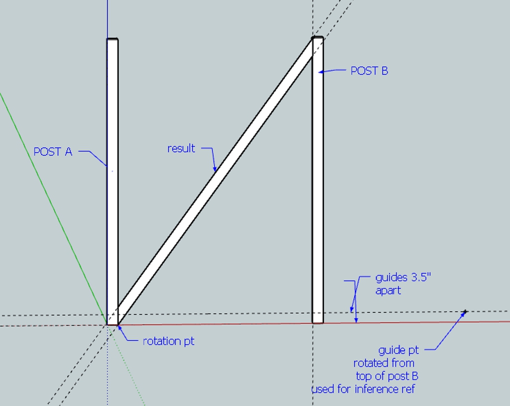
Here is the another closed form solution hcos( theta)-ssin(theta) = d
This can reudce to the form of sin(a-theta) = d/m
a= arctan(h/s)
m= is the polar mag of for your orginal post of s=65;h=96
d= lumber width ( 3.5) and if you implement my orginal post suggestion the modeled angle is 54.205( with more accurate guide point interpolation)
The actual angle is 54.178 the other intersect points are d/cos(theta), for the plum cuts) so can be laid out very quickly..IMHO you really don't need SU. Would be very easy to make cut schedule for various s,h and d -
RE: Mini-challenge
@jason_maranto said:
OK, I broke down and looked at the math on this -- it seems dirt simple to do so I think this is the solution (based on the math).
[attachment=0:n6vj9qbd]<!-- ia0 -->challenge solved.skp<!-- ia0 -->[/attachment:n6vj9qbd]
In this instance the desired width is 2 inches.
Best,
Jason.You have a closed form solution to this?
Hcos(theta)-d(1+cos(2theta)) /2-Ssin(theta)=0
Where H post height; d dimensional lumber width; s post spacing; theta rotation angle at post base.
If you have a closed form solution should not the measured width be exactly 2.00000??
IMHO all focus of the accuracy is questionable. Jeff is not building a watch. One will have to deal with dimensional lumber tolerance, crowning the lumber and maybe using a side winder to cut angles not to mention the angle layout. Maybe a good chop saw is at hand.??? -
RE: Mini-challenge
@tig said:
Mac1
How do you get the rotated guide pt to snap exactly onto the horizontal top guideline ?
The guide point and the guide lines are rotated ( their 3.5 spacing is used to get the intersect point on the post A bottom. The post B top is used for the snap ref. Have to do that since you cannot inference to guide lines. The error can occur on the other end when trying to get the guide point on the line. If you what more accuracy one could use the technique Jeane uses for interpolation to come close to the intersect point when rotating one line into another.
-
RE: Help modelling hyperbolic and catenoid type surfaces
@shpox said:
@mac1 said:
Jim Foltz has published an eq_grapher and once you have the 2d cure then generation of the 3d by follwme or TIGs extrude tools should be possible. The reason I mention this I have no idea what so ever if some of the surfaces above get the cure you want. You can get some of the conic sections by the intersection of a plane and cone. Hyperbolic is one. Maybe you don't care??
Thankyou for this. Although the accuracy of the curve/crescent don't need to be any particular height/length, I won't quite be using equations yet. What you have posted though will be super handy in assimilating these Triply periodic bicontinuous cubic microdomain morphologies: archive.msri.org/about/sgp/jim/papers/morphbysymmetry/table/index.html
Beats have to use the ruby console. The big intention is so create architectural spaces through these minimal surfaces.
@unknownuser said:
But seems you will have a better and simple result (rectangular faces) with only the Follow me

[attachment=1:2msqbybj]<!-- ia1 -->late1.jpg<!-- ia1 -->[/attachment:2msqbybj]Thanks for your diagrams. They were very helpful. Using the follow me definetly seems a bit easier. The only possible issue is creating the depth in the catenoid. I'd technically have to assume the same elevation 'crescent' to ensure each catenoid is uniform in width. This may present issues if I'm attempting to make a loft between two circles of unequal length, in which curviloft maybe be more suitable.
May I ask if you used any plugin to color all the facets of your catenoid? Or if it was done manually

I've also search the web to find ways to flatten curved surfaces. So far, no easy solution or luck

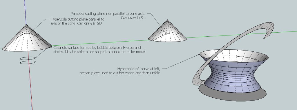
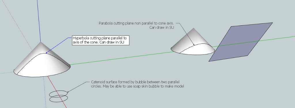
You do not have to use equations for the hyperbola or the parabola and if fact for any of conic sections( circle, ellipse, parabola and the hyperbola ( single or double sheet). These come from the intersection of plane and cone and you can draw them using the native SU tools. For the catenary your are stuck. You either use several plugins, plot in excel and then import the x/y values to SU, or use soap skin bubble but I am not sure this will work. It is defined by the hyperbolic cosine function as y = cosh(x/a) or y = a/2( exp(x/a)+exp(-x/a)) where a is the ratio of the cable tension to unit length weight). A small value results in a "pointy" curve. As a designer you need to decide what you want and then go form there. I think it is close to a hyperbola so maybe use only that. Again that is choices you have to make as designer.
Some surfaces are not unfold-able but I have not none the research if any of these fit that category. That is your job as designer.You are expanding considerably your original post with this last one. You have been given the info you need now have fun!
BTW: There even online calculators for the catenary or tables the power companies et. al. use also.
[attachment=0:2msqbybj]<!-- ia0 -->conic section_2.jpg<!-- ia0 -->[/attachment:2msqbybj]
This is my first shot at unfold. Try the same approach by vertical slices it nay be better.
**Update 4-15 1319 MST
Some search for self education found the following:- Warped and double curve surfaces are non- developable( spheres are double curved and hyperboloid and paraboloid double warped) meaning they cannot be created with the unfold tool like you are trying to accomplish. A sphere is double curved and we all know how baseballs are made=> with the odd shaped covers. Spheres are also developed by treating the "gores" like cylinders and laying them out that way. You can use the unfold tool to make one gore ( for the hyperboloid and paraboloid) and then you would have to bend and glue a number together with probably questionable results. A clay model should be easy( just like the follow me tool) to make, you could submit to 3 d printing($) , or ribs and then attachment of some type of flexible materail. Crazy thoughts. [ /b]
Hope someone with more knowledge base weights in on this??**
-
RE: Help modelling hyperbolic and catenoid type surfaces
Here is what I think the curves need to be unless you don't really care about the conic section. -
RE: Help modelling hyperbolic and catenoid type surfaces
Jim Foltz has published an eq_grapher and once you have the 2d cure then generation of the 3d by follwme or TIGs extrude tools should be possible. The reason I mention this I have no idea what so ever if some of the surfaces above get the cure you want. You can get some of the conic sections by the intersection of a plane and cone. Hyperbolic is one. Maybe you don't care??
-
RE: Sketchup computer - selection guidelines
@sketchymick said:
@mac1 said:
Couple other comments / factoids for you:
.....OK interesting stuff... thanks. I've sent you a PM with email address if there's more you can send.
The system I'm currently looking at putting together is based on i7-3930 (3.2 GHz), Quadro 2000, WinPro64. I will definitely put in a SSD for the system and programs drive, but probably just a normal HDD for data due to cost. Probably 16Gb memory since RAM is comparatively cheap. I've read your links... to me it seems there isn't a whole that that can be done about devices needing memory - you just have to account for it and be aware of the system limits? Right? I'd be interested in comments about the graphics card (it has openGL 4.0), some say go with a consumer card, others say go with a workstation card because the drivers are better - this has been one of my biggest conundrums.
Heat is one thing that has been really bugging me lately, I have a dell studio laptop that pumps heat out the back like a hairdryer, and I've noticed also the power supply warms up quite significantly. Obviously can't be good for the machine - so getting a laptop cooler for that one, and will make sure the new computer is well cooled.
Cheers
- Mick
Make sure you look at the sku version of windows7 64/32 bit installed. Although 64 bit machines could address TB MS does not have test capability for that and some version limit down to as low as 2GB.( That is for W7 32 bits though). Looks like you are OK. Here is the memory limits for various releases but would have to check for updates http://msdn.microsoft.com/en-us/library/aa366778%28v=vs.85%29.aspx Make sure you check the current state. SSD split is correct way. Crucial( I don't have a link so check their web site) has a set up wherein you can make a clone of the present drive and then it is just a mechanical switch.They supply the software, conversion rails and the SBU cable. Make sure you take the time to partition the new drives so it is easy to separate the two. You may have to do a reorginization of your present file tree. This may help http://www.techsuportalert.com and look for "Never re-install Windows Again" Part 1, 2 and 3. A 256 GB SSD maybe ok?
Isn't it ironic lap tops are small for portability and now you need a cooler
I have not done enough reading on the deprecation of OpenGL and what the implications to SU are. I think that is some thing Google owes their users to answer and especially the MAC users. I think I'll post a question to them on their help forum -
RE: Sketchup computer - selection guidelines
@sketchymick said:
@mac1 said:
I have personally included the 4Gb switch I my boot init file and have been able to open 340 MB files. That is documented in my postings: a number of post have cited the same LA; the issue of some programs not being able to efficiently use massive parrelel CPU has been around for a number of years and if you read some of the Google post they state it will not use dual cores. Again search some of my post wherein I gave ref to the testing showing thw 4x problem
Why don't you ask the same questions to the poster you cited??OK thanks, I'm not doubting your information at all, in fact it is very helpful and had in fact bookmarked one page on 4GB Patch that I noticed you'd contributed to, I was just curious if there was one core reference out there that I couldn't find. I'll have a look at your other posts, and I have actually emailed the other author as you suggested but no reply as yet. Thanks - Mick
Couple other comments / factoids for you:
- Do not forget about solid state hard drives. I built my present machine about 6 years ago. A P4 running 3.2 GHz CPU , 4 GB RAM and the biggest /cheapest performance improve I could do now would be to install a solid state hard drive. They are still a little pricey;
- Upper limit on CPU is around 3.5 GHZ. If you visit some of the shopping mall computer stores just feel the bottom of some of the lap tops and some will be really warm ( almost hot). There have been some complaints in this area. Think some suppliers are trying to get a around this by clock rate switching.
- I'll see if I can find the single core vs dual task speed test and e mail to you if I can find it. If your profile does not have your e mail address e mail me so I can get it;
- If you have not read the links I sent you read them they are full of good info. Plan to spend some time they make your eyes glass over

- If my memory serves me the 4 GB switch only works for INTEL MBs. They comment in the supplied links. Those links also cover how device drivers eat up memory. I have seen post where people go to 64 bit machine and then install a lots of graphics memory and use up a good chunk of the extra memory they just bought. Most do not under stand this. Links covers that also.
- This maybe out of scope of your effort ,but I think there is a major issue coming with SU and the OpenGL. The OpenGL folks have started to move toward non-downward compatibility. In fact Apple Lion machines have either OpenGL 2.1 or 3.3 where 3.3 is not downward compatible. My suspicion of some Lion machine / SU problems may be caused by this but my post comments go ignored. I need to do more reading in this area.
-
RE: Sketchup computer - selection guidelines
@sketchymick said:
@mac1 said:
Read all of these http://blogs.technet.com/b/markrussinovich/archive/2008/07/21/3092070.aspx
I was thinking specifically about sketchup... in other words how do we know it is "large block address aware"? How do we know that it only uses 1 processor? that's the sort of thing I meant. Cheers - Mick
I have personally included the 4Gb switch I my boot init file and have been able to open 340 MB files. That is documented in my postings: a number of post have cited the same LA; the issue of some programs not being able to efficiently use massive parrelel CPU has been around for a number of years and if you read some of the Google post they state it will not use dual cores. Again search some of my post wherein I gave ref to the testing showing thw 4x problem
Why don't you ask the same questions to the poster you cited?? -
RE: Sketchup computer - selection guidelines
@sketchymick said:
@mac1 said:
Ref 64 bit machines. Su does run as a 32 bit but but is large block address aware and as such can use more memory and in fact on my 32 bit P4 I can set the boot init to allow SU to use 3GB memory
OK that's interesting... so how does one come across such information? I've been searching and have only found little scraps of information here and there. Cheers - Mick
Read all of these http://blogs.technet.com/b/markrussinovich/archive/2008/07/21/3092070.aspx
-
RE: Sketchup computer - selection guidelines
@sketchymick said:
Hi,
It's time for a computer upgrade... in terms of specs for sketchup use, I came across this link http://www.vtc.com/products/GoogleSketchUpPro8/Introduction/99227 which seems to have good information - the highlights of which are:
- you don't need a multicore processor for SketchUp and because SketchUp only uses 1 core
- you're better off buying a 1 or 2 core processor that has a high clock speed
- don't worry about purchasing a 64-bit operating system with heaps of RAM as sketchUp operates as a 32-bit application and can only use 2Gb.
- there's really two video cards to consider: ATI FirePro and Nvidia Quadro...go for workstation cards because of the quality of the OpenGL drivers (and other things).
Is all this accurate? Anything to add?
Also relevant to my choice of computer.... at the moment I don't do any rendering, but might in the future. Probably also be using a bit of autocad (civil 3D if anyone here has had the misfortune of using it!) and I deal with very large spreadsheets.
Thanks
- Mick
Ref 64 bit machines. Su does run as a 32 bit but but is large block address aware and as such can use more memory and in fact on my 32 bit P4 I can set the boot init to allow SU to use 3GB memory
-
RE: Hull Design
@kenanaybati said:
Hi all,
I have just started to model ships, it is a correct way to make a hull?
It's a piece of 'hull'
[attachment=0:2ew50a1m]<!-- ia0 -->hull.jpg<!-- ia0 -->[/attachment:2ew50a1m]
The short answer is no usually splines are used. See these links for tut and free software.
http://www.delftship.net/delftship/index.php/downloads/viewcategory/3-delftship-software
http://www.delftship.net/delftship/index.php/downloads. These should give the ideas of approach and how Su can be used also.
Clarification 4-7
I am not suggesting you use Delftship but rather as some reading so you know what the design process is and the "jargon" used so then you have some concept of what needs to be done in SU. There are some very nice SU models posted and they can be done ,but what I see in your initial post may very well give you some down stream problems. -
RE: Printing problems
Rhots:
There are some concepts which may help to understand what is happening:- What is printed is the screen image and not the model. The display nor your printer under stand model size. They work strictly in pixes / dots per inch;
- For the fit to page print what you see for page size is not the model but the screen size SU has calculated based on its knowledge of the model ize and the pixels size of your screen settings;
- SU then uses that information and the printer settings to determine the scaling it must a apply to print the screen to your specified paper size and thus the scaling you see in the left scaling box.
BTW I would suggest you toogle the use screen extents several times until the the page size report is consistent. ( I think there is a bug here because this and the zoom extents in the SU window give different results. )
In addition related to your comment about dimensions disappearing check what you have set in the expert dimension dialog box. There is an option of not printing when they get too small.
I would suggest you make a simple rectangle model with an aspect ratio consistent with you screen (2d) and then make its size very close to the paper size and check out what is happening including change of print format.
Just some thoughts based on what I think I know
-
RE: My week-end challenge and DC problems
@unknownuser said:
Here is a little guide to understand the variables :
[attachment=0:20dsmooa]<!-- ia0 -->02_1.jpg<!-- ia0 -->[/attachment:20dsmooa]
All the variables don't change the shape of the bridge, only the calculation.
Only Course, La and Lb are variables ; Angles are calculated with them.Instead of checking sin(a) have you considered checking the angle. There are only a few cases( maybe only a=0) that would need checking constrained by your geo. Conversely can't you create a variable say z= sin(a) and do a check on that?? you could even go as far as using a taylor series exapnsion for all if SU has problem with small angles.
-
RE: Sketchup is Inacurrate???
@noelwarr said:
Wow! Lots of posts. Think I've read through them all but I don't think the following has been pointed out... Sketchup is based on floating point data structure. These are inherently inaccurate. Try the following out in the ruby console
(Math::PI).to_l
=> 3.14159265358979
(Math::PI * 10**13).to_l
=> 31415926535897.9This means that the further away from the origin your entities are, the more inaccurate they are.
Floats are a lightweight data structure ideal for a program like Sketchup. There are others that are actually capable of manipulating irrational numbers (pi, square root of two...check out GMP) without ever loosing accuracy but they are very heavy weight and only really necessary if you're, I don't know, sending a rocket to the moon or something.
Sketchup overcomes this floating point inaccuracy by allowing for a little tollerance but as you can see the difference is still there
point1.to_s + point2.to_s
=> (258,878708mm, 172,933835mm, 0mm)(0mm, 0mm, 0mm)
point1.z == point2.z
=> true
point1.to_a
=> [10.1920751212053, 6.80841870273468, 1.77635683940025e-015]
point2.to_a
=> [0.0, 0.0, 0.0]Nonetheless Sketchup is a great tool and its inaccuracy (that is also present in those other "more professional" packages!) can be overlooked 99% of the time. Hope this was of use to anyone.
See my 3-16 post above and has been addressed before. The reason some packages show more accuracy the spec allows for extened or extendable implimentations. The single float 32 is only good to 7.225 digits.