sketchucation logo sketchucation
    • Login
    1. Home
    2. mac1
    3. Posts
    Oops, your profile's looking a bit empty! To help us tailor your experience, please fill in key details like your SketchUp version, skill level, operating system, and more. Update and save your info on your profile page today!
    πŸ”Œ Easy Offset | Offset selected faces in SketchUp in positive and negative offsets. Download
    M
    Offline
    • Profile
    • Following 0
    • Followers 0
    • Topics 7
    • Posts 872
    • Groups 1

    Posts

    Recent Best Controversial
    • RE: Terrain from contours - improve on native 'from contours'?

      @brookefox said:

      TIG and Didier both have contour makers posted at Didier's site, that make contours from faces. So in my backwards world I make a terrain with SU 'from contours' (5' intervals), then I interpolate contours from that terrain with one of these plugins (1' contours), then I quad skin those contours. All to get a more manipulable and better looking terrain. (I can't seem to loft the original contours directly with curviloft.)

      Sorry I mislead you with my ref to the poisson mesh and did not mean you use it. Rightly or wrongly I think you are trying to get to a particular problem related to a model you have tried to make and the question is toward that end. Esoteric questions ( which I think this is.) usually lead to those type of answers and may not solve the real problem. If correct suggest you present your problem model and let posters try and answer? Is this related to your post http://forums.sketchucation.com/viewtopic.php?f=11&t=44181&p=394442#p394442 ??
      I have not tried Tigs plugin in but did use Didiers and it worked well although I think its is more decimation focused then interpolation. I question if Curviloft is the correct approach for this application. Here is a pic but based on this post thing going the wrong direction?
      Decimated using terrain_reshaper resulting in large tris.

      posted in SketchUp Discussions
      M
      mac1
    • RE: Terrain from contours - improve on native 'from contours'?

      mesh.jpg
      @brookefox said:

      Thank you, mac1. These are redrawn contours, originally at 5' intervals, from a quad map. My original "improve on" is vague and unclear, and I recognized that. 'Make a more useable model' would be better, as those terms are generally construed. Give it yer best shot, why not?. 'Complex-ify' the contours if you like; I maintain that will not help as that is the way it was before it was simplified. Interpolating additional contours, though not adding accuracy, would seemingly improve useability.

      Ok here you are. On the left is a poisson mesh ( with the "leg" on right πŸ˜† 
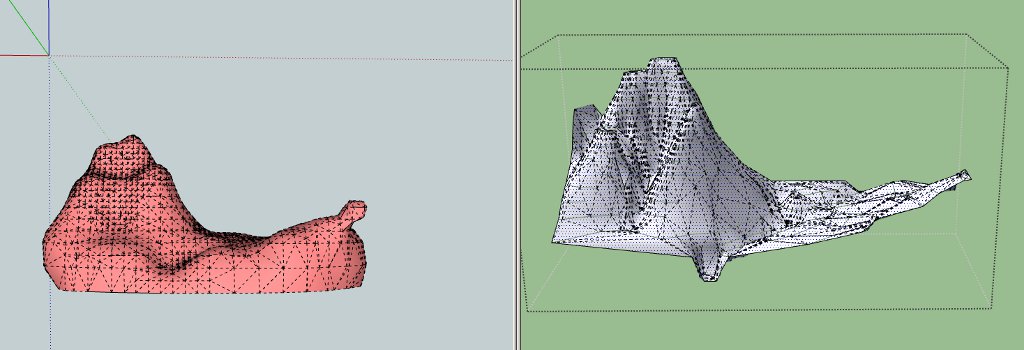
basede on first shot. There are many parameters that could be changed ) form the vertices of your data and the right the SU mesh created from contours and demonstrates the issue I was addressing. If I ask which is more "useable " for you I am sure what the answer would be:"This left one does not look right and so back to square one." If I am creating a Mesh from vertical walls the SU created mesh I am sure you will say is not usable. IMHO what you are asking is some what out side the intent of the SU program and the criteria of useful is to subjective. Maybe that is the way it has to be?? or use the tools it provides and edit its mesh to meet your needs. Have you seen this http://www.valiarchitects.com/sketchup_scripts/instant-road ?

      posted in SketchUp Discussions
      M
      mac1
    • RE: Terrain from contours - improve on native 'from contours'?

      I am not sure the issue is improving the SU tool but what is the intergerty of the data used. When sampling is used the sample frequency ( In my world of engineering it is called the Nyquist frequency) must be higher to accurately represent the geometry ( high frequency ) one is dealing with so if that information is not provided then any thing you do in SU will be fooling your self. I am sure if you are interested then some moderate search will give you the basis to define what you mean "by improve on" and data thinning of the model as presented IMO does nothing to help define the problem.
      If the question is related to the number of segments used in each contour then you will still have the same problem since the # segs is directly related to the above. However if you are not concerned about contour accuray the there are filters which can either decimate , smooth , interpolate or even make the number or segs the same for each contour line, and cubic spline interpolation between points etc??. These last two would be on a per line basis and a lots of work for the user

      posted in SketchUp Discussions
      M
      mac1
    • RE: Printing problems

      you stated you do not care about scale so why not use the fit to page option??

      posted in SketchUp Discussions
      M
      mac1
    • RE: Edge Question

      upstairs_downstairs2.skp. BTW not my tut.
      See if this helps

      posted in SketchUp Discussions
      M
      mac1
    • RE: Complex shape pushpulled?

      Use this plugin http://www.smustard.com/script/StrayLines. It is very useful to find those stray lines you cannot see unless zoomed way in.

      posted in Newbie Forum
      M
      mac1
    • RE: Sketchup is Inacurrate???

      @edson said:

      a couple of decades ago solar energy had a bad reputation in brasil as being inefficient. it turned out it did not work because the people who introduced it to us had no idea as to how to make it work: panels very seldom faced the correct direction and the height relationship among the parts was wrong. as soon as cleverer people started dealing in it solar energy become known for what it is.

      could something similar happen at times with sketchup users? I remember hearing a colleague at my university say it was a pity sketchup could not be used to produce precise models... πŸ˜’

      It was well known back then of the geometery relations the real issue was the efficiency of the cells . Look at the helio stat array

      posted in SketchUp Discussions
      M
      mac1
    • RE: Sketchup is Inacurrate???

      I have searched more than once for Google backup for all these number limits thrown around.
      Have you ever seen any?
      The floating point has a accuracy of 7.+ digits so I don't know where the developers get the 1/ 1000 value and does that not mena it is not a 32 bit application as stated? You will see more digits reported (like the value I listed above form a float 32 online IEEE 754 Single precision 32 bit conversion ) and there was a post not long ago about Google changing the conversion in dae for inch to cm to 2. 53999969330360 which causes then the file to use a more storage and considerable larger file size.I don't think that change was necessary , but again could find zero SU8M2 release notes on that issue.
      In fact some processors ( non 64 machines aka my P4 CPU ) will use 64 bits but then gets reduced to 32 bits when the value is stored.

      posted in SketchUp Discussions
      M
      mac1
    • RE: Sketchup is Inacurrate???

      Is SU inaccurate. The answer is YES. IT is a digital machine and they all have an native inaccuracy and then quite often some program design "quirks". It is up to the user then to understand and decide if what is provided is adequate for their intended application. If one is really interested in the native accuracy look up IEEE 754 Single Precision 32 bit and you will find numerous papers on the subject. There are pathological cases where large errors can occur.

      posted in SketchUp Discussions
      M
      mac1
    • RE: Raster to Vector Conversion... any new advances?

      @krisidious said:

      that seems to get pretty close. I'm going to play around with it.

      What Charly posted looks good and conversion to dae and then to MeshLab looks OK also=> for quick check.
      Suggestion: Contact the seller and see if they will convert your posted test jpg since you may be interested in buying a license ? => just as an eval. test. My guess they will want you to re-scan that image to tif , not re-sample. The key to success is to have a clean image to start and if you have a number you want to convert you will have to factor that into your plans. If you can get to a somewhat decent SU ( then Dae) then Meshlab may be used to remove T vertices etc. I could not clean you ordinal test jpg to a clean level to work with.

      posted in Corner Bar
      M
      mac1
    • RE: Raster to Vector Conversion... any new advances?

      raster _vector_GBa.skpA baby step. How does this compare to your best case?
      Clean up now using Meshlab or some plugins?

      posted in Corner Bar
      M
      mac1
    • RE: How to fold a plane around a curved surface?

      It would help greatly if you posted your model or portions thereof so we know what you are really trying to do. Otherwise it is a guessing game πŸ˜’

      posted in Woodworking
      M
      mac1
    • RE: Raster to Vector Conversion... any new advances?

      Will not give up yet. With all the advances in imaging technology, both over head and medical, one would think some thing is out there. GIMP uses canney, sobel and lapacian algorithms plus some others to detect. WinTopo has some too. Will have to see??

      posted in Corner Bar
      M
      mac1
    • RE: Raster to Vector Conversion... any new advances?

      [here are some results:
      Test raster _vector.skp The skp file is not usable.\My license for WinTopo expired so did this with free version.
      The jpg you posted has a number of problems:

      1. It is a JPEG and it should have been save in a better format; sample size probably too large( I would probably try to interpolate: typical ACAD problems, many overlaps, some speckle. To do what you want would require some pre processing to clean the images
      2. Here are some of the results of the GIMP edge detection:I had to interpolate to allow post here
        attachment=0]MainFlrII-Edge Detect down sample.jpg[/attachment]

      MainFlrII-Edge Detect down sample.jpg

      posted in Corner Bar
      M
      mac1
    • RE: High Core temperature

      Several other ideas; / comments. For good reliable design we usually try and keep the base emitter junction temp below 125C, there is a thermal resistance from that point to the mounting base. The magnitude of the temp difference and the base temp depends on the dissipation and that resistance. Don't neglect the air filter and cleaning them. My machine has a air tunnel running from out side thru a filter directly to the top of the CPU where the fan is installed so make sure you don't have any obstructions that would prevent heat flow from or air intake to your PC. For a lap top the base will be an area for high heat conduction so don't thermally isolate it. Feel around your case and you can probably feel the hot spot so even have a fan blow on that could help. I would not be surprised if the funny sound is coming form the fan bearings which are usually not very good. I recently hand noise from my graphics fan so I lubricated them => that probably would make the manf. frown but it worked! Can you monitor fan speed and even set it to run at a higher speed? That may be a BIOS setup item =>mine has that. May desk top has a spot for an addition fan. That may also be a consideration for you.
      You did not mention the PC manufacture. There have been some reports of high heat I have read so check your maker, the mother board spec / with them on limits and search the internet for his design.
      Just some thoughts.

      posted in V-Ray
      M
      mac1
    • RE: Raster to Vector Conversion... any new advances?

      Do you have a typical example you can post? I some times use GIMP in an edge detect mode( for simple things), and then Wintopo to convert from raster to vector. Wintopo would probably lose its mind if you have extraneous " things".

      posted in Corner Bar
      M
      mac1
    • RE: How to fold a plane around a curved surface?

      Got It Dave. Like me when all else fails hire some one πŸ’š
      Is he the same guy that makes the curved glass for you ❓ ❓

      posted in Woodworking
      M
      mac1
    • RE: How to fold a plane around a curved surface?

      TIG is on the money. It appears to me the confusion comes from the fact the OP presents the windows on developed surface which one gets when the surface of a cone is developed =>aka fattened. In actually one needs to ask the question how would this been done for an actual build or does one care?? The issue with the intersection I did not like when tried initially is the widows stiles will be warped because one is dealing with a double curved surface
      Dave R. how would you actually build this??

      posted in Woodworking
      M
      mac1
    • RE: Engraved sign maker, technique, or plugin

      @tspco said:

      Ok Dan I tried this as I understand it, I used the pencil tool as a center finder.
      The panel is no problem, the problem is the text object. I grabbed a random serif font, didn't change the text so it reads ENTER TEXT. I picked up component center inference dots. No dots on the "E" characters, and I picked up the center of the"T" characters two centers on the "N, R, and X" one on each "foot".
      What I have done in the past to center a text component on a face, is place the component at "eyeball center". Then using the tape measure tool, move in from both sides from the edge of the panel to the widest part of the first, and last letter. Then subtract the smaller measurement from the larger, divide the result by two then move the text in the correct direction, that amount. Well, this technique doesn't work 100% of the time sometimes I need to repeat the procedure. That is an operator error thing. Not working for me right now.

      A different thought that does not limit you to the SU 3d text. Using a candidate jgp and jpg photo editor like GIMP to edge detect then use WinTopo to convert to a vector file vs raster. You can then open this with SU( probably have to go through CAD first because WinTopo can not export to SU ) and use push pull etc to create the desired sign. Very complex graphics gets problematic.

      posted in Plugins
      M
      mac1
    • RE: How to fold a plane around a curved surface?

      Look at the plugin tools on surface or just draw widow and then extrude thru dodger and intersect. You have a window plane intersecting with what looks like a truncated cone and the intersect should give the vertical sloped lines you want ?
      You could also draw them with the line tool( make sure you use the correct inference). However from the pronounced arc at the their bottom I think you are using very high poly surface. Is it possible to post model at least the dodger portion?
      Here is one concept using the line tool. Only one window drawn the rest made with radial copy. Not the lat line for ref.
      dodger windows.jpg

      posted in Woodworking
      M
      mac1
    • 1
    • 2
    • 16
    • 17
    • 18
    • 19
    • 20
    • 43
    • 44
    • 18 / 44