sketchucation logo sketchucation
    • Login
    1. Home
    2. jgb
    3. Posts
    Oops, your profile's looking a bit empty! To help us tailor your experience, please fill in key details like your SketchUp version, skill level, operating system, and more. Update and save your info on your profile page today!
    โš ๏ธ Important | Libfredo 15.8b introduces important bugfixes for Fredo's Extensions Update
    Offline
    • Profile
    • Following 0
    • Followers 0
    • Topics 73
    • Posts 803
    • Groups 1

    Posts

    Recent Best Controversial
    • RE: SU 9 Wishlist

      @2harry2 said:

      1. The ability to force a snap to a specific point, especially a mid-point or circle center, instead of having to estimate by eye and hover the cursor over your best guess, which sometimes takes a while, and sometimes doesn't seem to work at all.

      2. Making the zoom function behave logically when the cursor is over empty space (as someone else already pointed out)

      Point #1, SU will readily snap to a circles center if you run the cursor around the circumference then hover near the perceived center. Won't work on exploded curves.

      #2; Been bitchin about this for 3 years now; others probably longer. SU Development will rather add more bells and whistles than tune up existing cracked bells and blocked whistles.

      posted in SketchUp Feature Requests
      jgbJ
      jgb
    • RE: Question regarding push-pull tool

      Well I found some (little) time to play a bit with JPP and ........

      After about 10 minutes playing with JPP, I did a simulated fuselage nose skin section, and then pulled the outer surface in an inch (thicken) in under 10 seconds. Took me over an hour to do that before using the copy, scale in 3 axis, join the edges, then tweak it into shape. Sticking a door into the fuselage (which is 3 inches thick with a window) took a minute to draw it in and 15 seconds to make the door group, versus over an hour before to get that same shape, but with many minor errors.

      This has got to be one of the 10 all time best plug-ins for SU, and really should be an integral part of the next SU version release.

      Now I gotta spend some time with it, and tweak some defaults as described in the thread and documentation, which incidentally is also the best written for a plug-in I've seen yet. ๐Ÿ‘ ๐Ÿ‘ ๐Ÿ‘

      Now my biggest problem is whether I go back and redo many of my airplane models and rid them of my manual error ridden thick panels. In one major case that's a 90% redraw, but probably worth it.

      Fredo.... THANK YOU THANK YOU THANK YOU

      posted in Newbie Forum
      jgbJ
      jgb
    • RE: [Plugin] Solid Inspector

      Thomthom said "I have plans (desire) to......"

      I know THAT feeling all too well. ๐Ÿ˜†

      posted in Plugins
      jgbJ
      jgb
    • RE: [Plugin] Solid Inspector

      @alencar said:

      Dear Thomthom

      is amazing how a simple program can solve such a complex issue and recurrent.

      this is brilliant

      thank you, very much.

      Believe me, Solid Inspector is not a "simple" program by a long shot. ๐Ÿ‘ ๐Ÿ‘ ๐Ÿ‘

      TT has displayed an ongoing expertise in solving problems in SU that should have been an intrinsic part of SU from the get-go.

      Using SI as a prime example; SU's attempt at being a solid modeler is commendable, however, to allow the tiniest errant fragment to prevent a solid from "forming" and NOT TELLING YOU WHY is amateurish at the least. ๐Ÿ‘Š

      TT gets an A++++ for that fix.

      posted in Plugins
      jgbJ
      jgb
    • RE: How would you model this?

      @unknownuser said:

      @jgb said:

      Bidet (pronounced Bee-day

      The French would disagree.

      The French disagree with everyone, so what? Robin Williams (whom I think is the funniest man alive) got it right about that, but I fail to see where he enlightened us with the pronunciation.

      And Pilou, that photo is of what is commonly referred to (today) as a "Chamber-pot". There is no water washer as is common with Bidets'.

      Anyway, I think this topic is going down the tubes and we should flush it now. ๐Ÿคฃ

      posted in SketchUp Discussions
      jgbJ
      jgb
    • RE: Question regarding push-pull tool

      @gaieus said:

      Simple shell works with the scaling method so Joel's issues with the tapered part would still remain.

      JPP is not "perfect" either with too complex forms but mayyield better results with aeroplane hulls.

      Now you really have me curious. ๐ŸŽ‰

      posted in Newbie Forum
      jgbJ
      jgb
    • RE: Question regarding push-pull tool

      @numbthumb said:

      I think he was referring to Fredoยดs Joint Push Pull.

      Many thanks for the reference.

      Using SU for 3 years now and this is the first I've heard of Fredos JPP.

      So I just looked up that thread, and downloaded the files. Won't have time to try it for a while as I work for Elections Canada and an election was just called today. There goes all my free time between 8:30am and 9:30pm till 4 May. ๐Ÿ‘Ž

      Anyway, my best use of such a tool would be when I draw airplane skin parts. I normally draw to the moldline, then as almost all my designs use a 1/2 inch thick (or so) composite aeroshell, I copy the surface (inward) 1/2 inch then scale it to almost match the outer curve. My biggest problem is where the shell tapers at nose and tail. I cannot control the thickness ratio change using scale, which entails a lot of manual adjustment, let alone facing the edges, one line at a time.

      I just hope the JPP "thickening" function will do that job for me.

      posted in Newbie Forum
      jgbJ
      jgb
    • RE: How would you model this?

      @tig said:

      Rich

      It's a sluice for washing away 'dirty stuff' - NOT for 'number twos' directly produced over it... ๐Ÿ˜ฒ
      BUT the principle of its modeling remains the same........

      The common term for this device is a Bidet (pronounced Bee-day {French})

      Mind you the tube rack is novel, if seemingly a bit uncomfortable and perhaps impractical.
      Any Bidet I've seen uses a common toilet seat. You need to sit firmly down as it splashes a lot.

      posted in SketchUp Discussions
      jgbJ
      jgb
    • RE: Question regarding push-pull tool

      I would like to know HOW you got the push/pull tool to work on a curved surface? โ“ โ“ โ“

      In either direction.

      posted in Newbie Forum
      jgbJ
      jgb
    • RE: Dimensioning units - toggling between types

      Thank you

      Only problem was it screwed up my toolbar placement, and restore toolbars failed to correct that.

      posted in SketchUp Discussions
      jgbJ
      jgb
    • Dimensioning units - toggling between types

      I normally think and work in Feet-Inch-Decimal inch.
      SU gives you Feet-Inch-Fractional inch or just Inch-Decimal inch.

      Upto using V8, I would normally select Feet-Inch-Fractional working on buildings, and Inch-decimal on smaller stuff. SU is adept at taking any unit type on input, but only displays to what it is set to, so my VCB entries would look like 24'5.337.

      But now with V8 Solids, if I am working in inches it gives volume in Cubic Inches, and likewise, if in feet gives Cubic Feet, all quite logical. However, I, in my own logic, want to work in Inches but see volume in Cubic Feet. This necessitates my going into Model Info, selecting Units and toggling inches to feet. Then doing it all over again to revert.

      I can't create a shortcut to toggle.

      Is there a way to get SU to show Feet-Inch-Decimal units and then report volume in Cu.feet?
      Or create a shortcut or RUBY to toggle?

      posted in SketchUp Discussions sketchup
      jgbJ
      jgb
    • RE: [Plugin] Solid Inspector

      I've been using Solid Inspector for about 3 weeks now, and only a few days ago discovered the <tab> key, arrow key and <enter> functions. Never thought to look down. ๐Ÿ˜ฎ

      I use it so much I have the "S" key as a shortcut. ๐Ÿ‘

      But a most unintuitive aspect of SI is when it finds and highlights the problem(s). ๐Ÿ‘Ž

      Generally you want to delete the offender entity(s).
      The process is to toggle amongst the highlights to choose one, which is now indicated by a red circle. โ—
      Press <Enter> to zoom in on it.
      Place the white arrow cursor on the highlighted entity.
      Right click and select "Edit group". If you click "erase" here, it will delete the whole group.
      Keeping the cursor on the highlighted entity, Right Click and select "erase". That will delete the single cursor-ed entity only. Either 1 line or 1 face, but not the faces highlighted perimeter lines.
      And that leaves you in a form of limbo. ๐ŸŽ‰
      Now you have to select the "edit menu" and "close group" to get back into SI for the next problem.

      Since 99.9% of the time you want to simply delete the offending entity, why not simply;
      Place the cursor on it and just double click to delete the red highlighted entity.
      Then you toggle to the next.

      This obviates the wish for an auto-fix which is complex and where a simple deletion may not be the fix one needs to do.

      One other thing; when SI encounters a true solid (no errors) please say so, maybe a green circle around the group/comp. But do come out of the white arrow select mode.

      posted in Plugins
      jgbJ
      jgb
    • RE: What's your beginners tip?

      Dave said "if you make an extra copy of the component and scale it up before editing, you can discard the large copy when you've finished. No need to worry about scaling it back down and getting it in the right location." ๐Ÿ‘

      For the less experienced SU modelers, you need to scale up the copy of the component OUTSIDE its bounding box BEFORE you edit it. If you edit the comp, THEN scale it up, all copies will scale up as well.

      Anything you do to a comp on its bounding box, such as scale, rotate, apply material/color (and a few others) applies only to that particular copy of the comp. Anything you do to a comp IN edit mode applies to all copies.

      If you need to make a change to the geometry of only 1 copy, make it UNIQUE first, then edit. However that isolates that copy from any changes to/from other similar comps.

      posted in Newbie Forum
      jgbJ
      jgb
    • RE: What's your beginners tip?

      @dave r said:

      I only make components, not groups.

      No argument with that. I almost always end up converting a group to a comp when finished with its design.
      The main reason I keep groups is to cut down on the extensive list of comps (many of which would be sets of comps) I would create during the design. I use the groupings to segregate sections of geometry to avoid unwanted merging, then explode the group once done, but within a comp. I also usually group several comps into 1 coherent set, where I may have a slight difference in the set makeup in various places in the model. Groups and comps both have their advantages and should be used accordingly.

      posted in Newbie Forum
      jgbJ
      jgb
    • RE: What's your beginners tip?

      Regarding non-coplanar problems. If the attempt to face keeps failing, even after you have drawn and redrawn all the lines multiple times, here are a few ways to help find the culprit. Not always successful, but usually eliminates the co-linear line problem.

      If your triangular, rectangular or multi-line entity fails to face, you need to revert it to triangles. Draw lines from vertex to vertex, being careful to let SU tell you that you are using endpoints only, before you click. Zooming in helps, but if you encounter the clipping plane getting in close, then turn OFF perspective. (Camera; Perspective) Then you can get in real close.

      Another problem with drawing lines is where you are trying to draw a line (from A to B) that is not quite on-axis, and SU will tell you it is "constrained by line at point". Simply ESC and draw the line from B to A. Usually works. This is probably the biggest culprit creating co-linear lines.

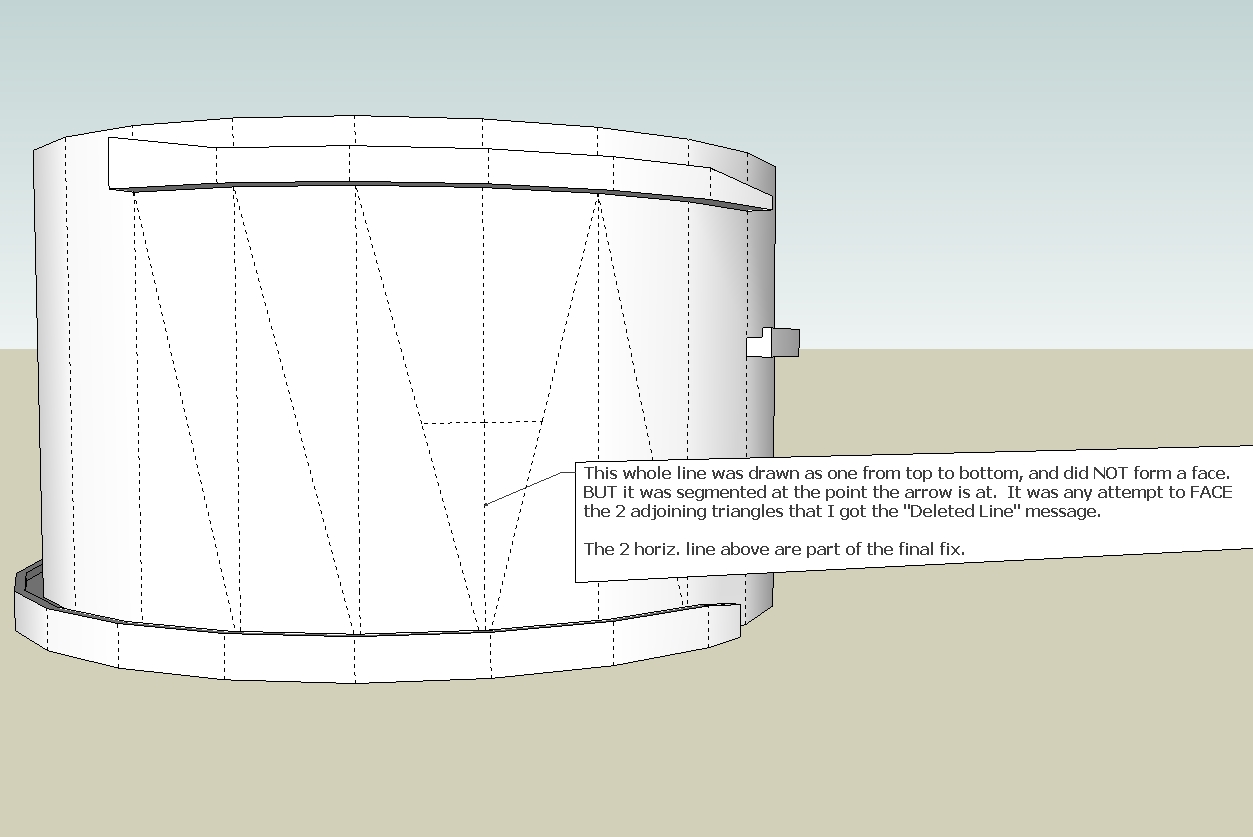
      Now let's say you do have a suspected co-linear line. You delete both of them, and redraw a single line, but the face still won't form. The culprit here is the tiny line segment formed at the vertex after the 2 co-linear lines were drawn. It can be nearly invisible unless you zoom in real close, and that takes time. So rather than go looking at all 3 corners for it, try this.

      Turn ON the Entity Info dialog box. You also need to turn on hidden lines. With the object viewed such that there are no other endpoints behind the suspect vertex, use the left to right select in a very small box just covering the vertex, and not any whole lines. If Entity Info says no selection, the problem is elsewhere. If the Entity Info says there is a very tiny line (or more than 1 line) then there is the problem. Just delete all of them. Do all 3 vertexes. This may deface other adjacent faces, but now you can delete a line and redraw it endpoint to endpoint to reform the faces.

      Note that this will NOT find a vertex gap, but deleting and redrawing lines at endpoints cleared of tiny fragments will cure the gaps.

      Another culprit is trying to face on a curve or arc line. Since there is no real endpoint within the length of the line, placing other lines to form a face may not be right on, and this can create a tiny fragment or gap to throw off the face. Just explode the curve/arc and that will help finding the true endpoints on the curve.

      When you have the whole object faced with triangles, you can start deleting the internal lines making all those triangles to get back to your multi-line face. If a face disappears doing this, then that triangle was not co-planar with the rest of the face, and you have to redraw that section in a co-planar manor. Or, just UNDO the deleted line, and make it soft and smooth (Entity Info box again).

      And with all that, I still spent 2 1/2 hours yesterday trying to get a triangle to face, and ending up deleting the whole section around it and starting over.

      posted in Newbie Forum
      jgbJ
      jgb
    • RE: WTF is &quot;Reference to Deleted Edge&quot;?????

      @tig said:

      Do you have some 'raw geometry' on various layers, some of which might be 'off' in the same location as these 'error edges' ?
      Layers do not separate geometry, but groups and components do.
      You may have something that is invisible or partially visible [like a face on an 'on' layer, with its edges on another 'off' layer].
      Always put 'raw geometry' on Layer0 and group/componentize them, and then give those a layer to control their visibility...

      Layering 'raw geometry' is the path to confusion... if not insanity.............. ๐Ÿ˜ฒ

      With all due respect Tig; I learned the hard way a long time ago about layers, layer0, groups and components. I NEVER draw on anything other than Layer0. One of the first things I did to troubleshoot was to toggle the layers with all lines visible just in case the line was hidden there. I even reset all the internal geometry to layer0, even though it was all on layer0 anyway.

      As I stated before, this group was drawn in totally virgin territory in my model. There was never any geometry even near where it was drawn. Also, it was always, since started as a raw circle, been a group, on its own development layer. ALL its internal raw geometry is always on Layer0, and there were no nested groups/comps within the group. Once the development reached a certain stage it was split up into several components to create copies in the overall model.

      There are 2 separate comps on another layer adjoining the central cylinder, the main floor ramp, and 3 copies of the ring ramps, which were created prior to the problem, but none of their geometry intersected with the problem phantom line.

      No matter what was redrawn, if any new line came near that phantom line, I got that message when I tried to face. The only way I was finally able to "fix" it was to draw a new set of faces (pyramid fashion) from the bounding edges with the vertex slightly projected out from the phantom line. Then I moved that vertex to line up the faces with the perimeter of the cylinder, hence those extra triangles in that area. That effectively killed the phantom line as I can no longer recreate the problem.

      I had the same problem in one other area, but that got fixed with just deleting the surrounding lines and redrawing them. But this one was real stubborn.

      posted in SketchUp Discussions
      jgbJ
      jgb
    • RE: WTF is &quot;Reference to Deleted Edge&quot;?????

      @mitcorb said:

      To date, I have not seen the message as you describe. But considering the amount of time I have spent with Sketchup, discovering its idiosyncracies, and the time I have spent studying the postings on this website trying to learn more, nothing surprises me with this program.
      I assume the condition occurred before you formed the eyebrow like projection above it?

      I read ya!

      It happened after the "eyebrows" were added. They are the inside support ledges for the actual ramp segments. This structure is the center core inside which the vent shaft is located.

      What you see is 1 story, out of the 3 parking levels. I was adding in the vent holes when the problem occurred. It is not finished by far. It next needs to be horizontally split in 4 rings, to be stacked 12 high. What you also do not yet see are the outside walls and columns on 3 sides supporting the ramp segments at their outer edges.

      posted in SketchUp Discussions
      jgbJ
      jgb
    • RE: WTF is &quot;Reference to Deleted Edge&quot;?????

      @mitcorb said:

      I didn't see mention of this- and maybe it doesn't relate- but when you need to form a single edge of two sequential segments, you know you can draw a line segment from the break, out into adjacent space a short distance. Then erase this segment. A single line segment should? be formed. What about some microscopic gap being somehow created in the process?

      I don't really understand what you mean, but there was no gap. It was a single line that for some reason SU8 broke into 2 lines. (See drawing). All those faces formed by triangles to either side resulted from the fix. They were 4 sided faces on the curve before I started to edit. The edit (a hole) is not yet reconstructed in the picture, and was to be centered just above the short horiz. line above the break point.

      From all the answers above, I suspect none of you has ever seen this message.. yes/no?


      Group_6.jpg

      posted in SketchUp Discussions
      jgbJ
      jgb
    • RE: WTF is &quot;Reference to Deleted Edge&quot;?????

      First, I fixed the problem yesterday by deleting and redrawing the whole section. But 1 line continued to become 2 segments even when I drew it as 1 long line. It segmented at the point where SU complained about the hidden line before, but this time I was able to "Create Face" by selecting the triangles perimeter (4 segments, rather than 3).

      However, I cannot replicate the error message in that area this morning, so sending you the model here will not accomplish anything, but if it recurs, I will, to this post to maintain the thread. It is a spiral ramp to a parking garage that I plan to put this on the warehouse as a module.

      So to answer questions, I do not get that message pop up as I draw. It happens when I modify an existing part of the model, and as I create the triangles, some fail to form the face. Usually it is a result of a tiny fragment separating the endpoints. That's now easy to fix, once I've found the culprit. Then I just select the 3 sides and "Create Face" Either the face forms, or I get the message "Create faces failed". BTW, I have a K/B shortcut "F" to Tools> Utilities> Create Face

      But in 2 instances in this group, and a very few other times in other models I get the "Reference to a Deleted line" message. Usually a redraw of the face perimeter fixed it, but this time, it took a lot of effort to fix, and that's only because I redrew a lot of surrounding geometry. The problem face was reconstructed from 6 triangles.

      The "Deleted line" is a mystery. There was never a "line" or any geometry at the point SU complained.
      It happened as I deleted a face on the side of a circular wall in order to insert some additional geometry. That particular set of entities did not meet my requirements, and was deleted. But the bounding 4 lines of the original face were never affected, so I tried to redraw 1 segment to reform the face, as I have done successfully many times before. That's when I got the message. I ended up deleting the 2 adjacent faces, which reformed immediately when I drew the 4th edge, but the face in the "deleted line" area had to be made up from The group was drawn fresh in totally virgin territory, and is contained within its own group from scratch.

      posted in SketchUp Discussions
      jgbJ
      jgb
    • WTF is &quot;Reference to Deleted Edge&quot;?????

      I Had a good solid, then I started editing it to add stuff. It stayed a solid;
      (Using "Solid Inspector" )
      I kept checking, then suddenly, it wasn't. So I hit Undo, and it was still not a solid. Then faces that were there before, no longer formed, even when I triangled them, endpoint to endpoint.

      And, here is the hair-pulling part (and I ain't got much left) when I deleted the lines and redrew the triangles, not only would the faces not form, but when I selected the 3 edges, and did FACE, I got this "Reference to Deleted Edge" every time.

      Not only that, when I redraw 1 line it becomes 2 segments of that line. I've tried all the Unhides I can find, but there is a phantom line in there.

      Now this object is grouped, and there are no penetrating other objects. All its geometry is on layer0 and its group is on its own layer.

      It seems V8 replaced some frustrating, but nonetheless almost useful error messages, to-wit "faces not planar" and "gap in perimeter" with a simple but totally useless message "Can't form face", and that "reference to deleted edge" which sounds informative, but it's not.

      Again, while SU can detect the errors, it gives you no clue or tools to fix them.

      posted in SketchUp Discussions sketchup
      jgbJ
      jgb
    • 1
    • 2
    • 30
    • 31
    • 32
    • 33
    • 34
    • 40
    • 41
    • 32 / 41