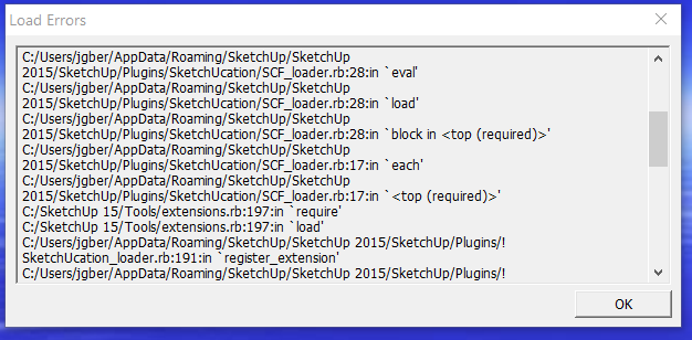
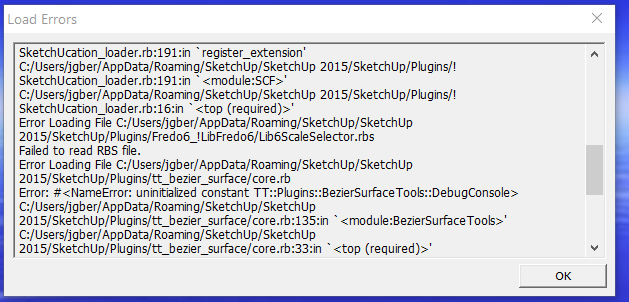
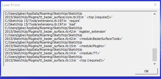
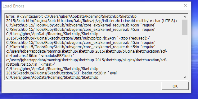
Thank you.
I will try them.
Posts made by jgb
-
RE: What versions of SU have .STL file export?
-
What versions of SU have .STL file export?
Right now I am stuck with SU 2015 Make on my PC that is win 10 32 bit.
I understand that SU 2016 is the last 32 bit I can load.
Does it support .STL file export?
If not is there an add-on or other app that can convert SU files to .STL? -
RE: Created faces from arcs
Curviloft is great, can't draw anything without it.
But it has a serious drawback if used to create printable surfaces. It does not join up opposing vertices if they are not of equal number of segments in the bounding curves, and even then not quite, You get a lot of extra lines on the curved surface, where I would spend a lot of time cleaning up, just to reduce my drawings line count. The curved surface looks just as good.
To combat that with some reasonably good success with Curviloft, make sure the long curves have an equal number of segments. If they are curves made up from more than one arc make sure the total segment count is the same for the curves. Do this in Entity Info. Providing the arc is pristine just change the segment count. Otherwise draw the arcs with a preset segment count that is consistent curve to curve.
Segment length also factors in to how well Curviloft makes a printable surface. Make sure all your line segments are greater in length than your print nozzle size, usually .4mm
Otherwise explode the curves and join vertices by hand making triangles.
For printing, preview the model with smoothing off, showing all hidden and smoothed lines before you export the STL file.
-
RE: Was told sketchup is bad for 3d printing
Although I have been using SU for near a decade now, I will only be getting a 3D printer in July/August, so I'm no expert on 3D printing. But I have done a lot of research on the subject.
The thing to remember in creating SU models that will print well is IMHO attention to detail.
SU is a surface modeller. Any curve is a series of straight line vectors, they are not the smooth curves you see if the model is smoothed. That smoothness is only an illusion via the SU display s/w.
The printer prints in straight lines, very small straight lines, but nothing is a true curve. So to get a reasonably smooth curve in the printer you need the curve divided into a lot of segments. SU default is 24 segments in a 360 degree circle. Great for small curves, but large curves may need 120 segments. That I think may be the reason some prints come out less than desired.
The other critical thing is the bead size the printer is making. The current standard .4mm so any feature Lines or curve segments) in the model that is less than .4mm will not print well, if at all. You can get print nozzles as small as .15mm, but that will really slow down a slow print to begin with. So making curves requires a minimum segment size no less than the nozzle size.
You need to preview the final model in SU with hidden and smoothed lines turned off before you output the STL file. That is what the print will/should look like.
-
RE: General Newbie Questions
Please allow me my $0.02 on this.
I know there are replies that covered what I will write, but long ago I made it simple to understand layers, groups and components.Layers are for visibility. LAYER 0 is your primary drawing layer.
There are very few reasons to draw or assign raw entities to any other layer, but in over 8 years, never found a good reason to.
More on layers further down.Groups and components are almost the same. In fact you could dispense with groups and use components exclusively. Groups/components are used to isolate entities within a bounding box. What happens to any other entity, group or component outside the box will not affect what's inside the box with the exception of components.
You draw entities. Lines, circles, squares, boxes, etc. You group or make a component of these entities to create a visual object. All of the entities that make this group/component are on LEVEL 0, including other groups/components that may make up the object.
You assign a layer to the GROUP/Component box that contains them.The difference is simple. Use a group if the drawn object only appears ONCE in the drawing. If you copy a group and make any changes to it or the entities inside, those changes apply only to the copy you changed.
Use a component if there is one or more copies of it in the drawing. If you copy a component, then any changes you make to the entities inside the component are reflected in every copy in the drawing, without exceptions.
Any changes you make to the component outside the box applies only to that changed component, such as layer, color, scale, orientation and a very few others.
You assign a layer to the bounding box of the group or component. All the stuff inside the box still remain on Layer 0, but their visibility is governed by the assigned layer of the box.
That's basically it, Layers are for visibility, groups are for a single collection of entities, component are for multiple instances of that collection.
OK, then how do you edit groups or components? You enter into edit mode and make whatever changes you need, exit and the group is changed and every component of that is changed as well. But if you want to make a change to only a single component, you make that component UNIQUE. Then edit it and the changes are only applied to that component.
Changes made to the other components will not affect this and vice versa.But supposing you had a pile of entities or group or component that you now wanted to be included with some other group or component.
Two ways; just make a group or component of all the parts you want. Then edit that new group/component and change the Layer of the contained entities to Layer 0, or you will have visibility problems later on. Unless there is a good reason to have different layers inside the box.
Or; Clipboard Copy the new stuff, edit the group/component and Paste In Place the clipboard copy. Exit and delete the stuff you clipped.
-
RE: [Plugin][$] Tools On Surface - v2.6a - 01 Apr 24
I take it that those roofs have the center raised a bit. The diagonal lines are the "hip" bends. Quite normal. You need to make then "soft" or hidden.
Three ways, either select the line and change its attribute in Entity Attributes; or
with the erase tool, press and hold "CTRL" and sweep over the line.
The third way is to create a layer and move those lines into it. Make that layer visible or invisible as needed.
-
RE: [Plugin][$] Tools On Surface - v2.6a - 01 Apr 24
What do you mean "sharp borders"?
-
RE: [Plugin][$] Tools On Surface - v2.6a - 01 Apr 24
I get that a lot too. Mentioned it numerous times in the past 8+ years and no improvement. Sometimes it works correctly, but I cannot define what works and what doesn't.
-
RE: Make an object stationary in viewspace
OK, I can live with that. It would be similar to a "material" I created for an airplane HUD that was transparent but with symbolic imagery. Just have to rethink what that logo would be in 2D.
Thanks to both of you. -
RE: Make an object stationary in viewspace
I'm missing something. It may be I'm using 2015 Make, but I can't find "create watermark".
I find "add watermark" but that takes me to materials to load a .JPG image.
I want to make a watermark from a drawn object. -
RE: Make an object stationary in viewspace
Pbacot; A background image would seem to move as the camera moves, and would be blocked by any object in between.
Dave; That seems like it might work. How do I make a watermark?
-
Make an object stationary in viewspace
This one stumps me.
I need to make an object remain stationary in viewspace, exactly like "un-pinned text".
I need to also be able to change view angles to all other objects as normally done when un-pinned text is visible.
Sorta like an object that always faces camera, but doesn't move either.
I want to put a stationary 3D logo on some of my model print exports.
Grouping an object with a text group doesn't work. The text moves with the object, but always faces camera. -
RE: Covering a complex area
You will need to break up the projected surface into several parts. Curviloft needs at least 3 segments to create a surface and that large shape is only one.
I do this sort of thing a lot, for airplane fuselages and fairings.
Just put a line vertex to vertex across each narrow part and curviloft (skin) each part separately. Don't do several at once.
For the end parts, just break the curve with 1 or 2 temporary short lines at vertices.
If CL scrambles the surface (quite common) break into smaller sections.
But be prepared to redo a lot of lines created by CL to smooth it out and reduce the lines count. I have redone some surfaces almost entirely, following the CL mapping, but with reduced lines that meet at vertices and not in mid line.
Then group all the section groups before exploding the curved surface section groups.
You may want to edit the vertices between each group to smooth it all out.Within the group, you can push/pull (not with the native SU push/pull) up to thicken the roof surface, then push/pull out to create the overhang/eaves.
-
RE: Can't create horizonatal guides
A tip....
Change the color of your guidelines to something not normally used in SU, like a medium orange. Not green, blue nor red. Yellow is hard to see as well.
Being black and dashed they tend to hide.
It would be nice if the guidelines could be 2 pixels wide, but, that ain't gonna happen. -
RE: [Plugin][$] Curviloft 2.0a - 31 Mar 24 (Loft & Skinning)
@fredo6 said:
@jgb said:
It's not that I have issues with CL in SU-2013, just I thought the latest CL update versions were 64 bit only. I will D/L the latest later this week.
In principle, Ruby script are independent from the OS details (hopefully), but sometimes dependent on the SketchUp version.
Thanks again. I'll now upgrade SU to 2016 (32bit) and all my plugins/extensions as well.
-
RE: [Plugin][$] Curviloft 2.0a - 31 Mar 24 (Loft & Skinning)
@fredo6 said:
@jgb said:
I wholeheartedly agree, but please also update your last 32 bit version as well.
I cannot run 64 bit apps on my old PC. I'm still running Make V.13.What do you mean?
Do you have issues with Curviloft on Sketchup 2013?It's not that I have issues with CL in SU-2013, just I thought the latest CL update versions were 64 bit only. I will D/L the latest later this week.
-
RE: [Plugin][$] Curviloft 2.0a - 31 Mar 24 (Loft & Skinning)
I really need to refresh the plugin with more explicit control of the different options (and maybe selecting a few ones which make sense).
I wholeheartedly agree, but please also update your last 32 bit version as well.
I cannot run 64 bit apps on my old PC. I'm still running Make V.13. -
RE: How to switch top to bottom of my model?
He wasn't exactly clear on what the final orientation should be, so flipping is just another way to do it.
-
RE: How to switch top to bottom of my model?
Select whole model, then Right Click and FLIP ALONG. Probably along Blue axis.
-
Toolbars won't stay fixed.
This problem was solved years ago, but now it's back (last 3-4 weeks ago).
I want my toolbars to stay where I put them, ie: Measurements defaults to the lower left. I put it in the lower right. It used to stay there between SU reboots, now it goes back to the left.
Other toolbars stay almost where I put them, except, I put a bit of space between them for clarity. When I reboot SU, they all move back to the left, except for a few that stay put on the right horizontal top row.
And the ones on the left side (vertical alignment) stay put.
Reset Toolbars has zero effect.
Really irritating.....
SU 15.3.3 (No, I can't go to 18 as I am locked into a 32 bit OS on my 64 bit PC; Long story)
Win 10 Home (32 bit)