Posts
-
RE: Adding thickness to a curviloft skin
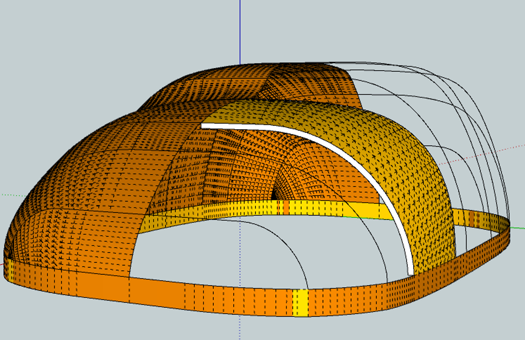
 Quick look at using TIGs extrude tool and offset for thickness.
Don't know which is best for your effort.
TIG has a new smart off set tool which maybe better than default one since it is problematic at times. -
RE: Time for a change for me...
Best of Luck

BTW no surfing here unless you want to ride waves in Boulder Creek.
Oh! Do not forget snow shovel, got rid of 20" in last few weeks, anti freeze for car @ - 30F will do + same for window washer. Snow suits for the young ones if you have any.
Moved from CA number of years ago and was treated by blizzard first day but you will enjoy ever minute. Great State , great people, family friendly and lots of out door activity. Don't get run over by Ralphie.
-
RE: Triangulation and Convex Polygons
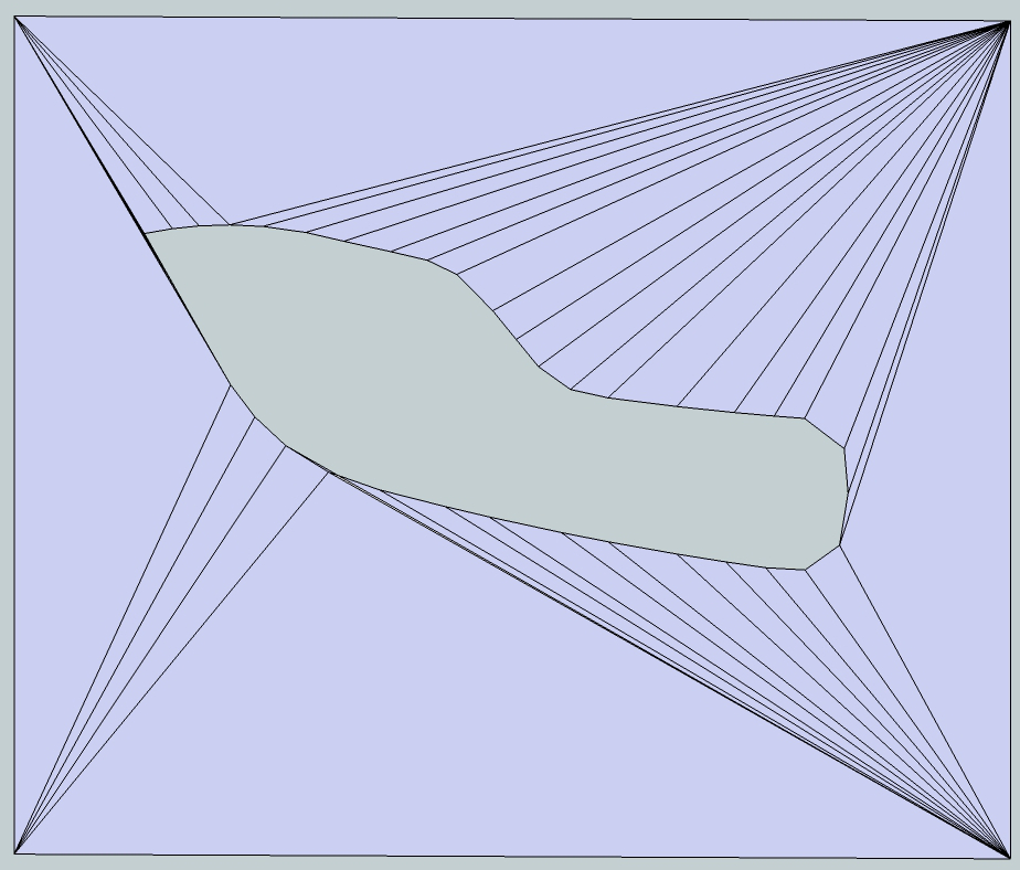
Will merging vertices help?
Your model reduced from 200+ to ~72

-
RE: Drawing a centrifugal pump volute
@jacbk612 said:
I plan to build up this pump completely with an impeller and everything and then run the Khamsin CFD plugin to see if I can get a nice real time simulation.
Gilles, is this something you are familiar with? Does this sound feasible?
Jacques
Gilles did a supper job of showing the approach. However, if you are going to spend the model effort and then simulation I would to suggest for your consideration:
Draw metal plugin will draw a volute for you vs using vs the two arcs. I used the radius shown in the drawing and 4turns to get a close fit then cut that to 1 turn.I think this approach will allow you to set the impeller differential spacing side to side more accurately. I spent some time trying to get better edge detection vs the raster dwg but no joy so far. TIF format would probably be better;
Khamsin has a YouTube video showing the simulation of a 250 cc kart. I was not able to find any definition for the system requirements but it was mentioned dual cores are required for some functions. In addition it has some 700,000 faces( as best as could tell) and appears to require 10+ hours to run. The point, make sure you look at your system, memory requirements etc so you know you have the hardware to run it.
Good Luck here is a link that may have data of interest to you http://www.hindawi.com/journals/ijrm/2011/137860/ -
RE: Sketchup orgin?
"Why worry about the speck in your brothers eye when you have a log in yours"? As I have often been told.
-
RE: Sketchup orgin?
If you want to see where the clipping planes are set, open model then consul and enter Sketchup.send_action 10624 ref http://sketchucation.com/forums/viewtopic.php?f=180&t=44076
-
RE: Sketchup orgin?
@pmolson said:
Gaieus,Mac 1,Daver
- The world axis does not effect clipping though...correct? Mine is set by template to my region, Minneapolis. When importing Google earth grab, that resets the world axis to the grab for that particular model if I am not mistaken.
Thanks
Correct. The WGS dataum does not curve fit some location good and they use a different datum. If you use their x,y data for your model in GE then location can be off meters.
For example WGS 0 meridian does not run through Greenwich. - The world axis does not effect clipping though...correct? Mine is set by template to my region, Minneapolis. When importing Google earth grab, that resets the world axis to the grab for that particular model if I am not mistaken.
-
RE: Sketchup orgin?
3d apps have clipping planes to reduce the rendering load on the CPU and/or GPU. There are 6 of these( top/bottom/ left/ right and front/back). In some cases there is occlusion culling also( back of buildings etc)The following are some of the question that come to mind( In the form of statements):
The field of view is important and should be set at about 25 degs. (per Su) but changing that could help your issue;
Minimization of rendering load should help per Daves suggestion above. However, my self question is: Is the clipping plane adaptive and changes if I turn layers on/ off or does one have to restart the program?;
Who sets the clipping planes, SU or the Graphics card, and does it change if hardware acceleration is on or off?
Given parts of the model are not displayed behind the section plane can that be used to help this problem;
For large model extents the use of scenes can be used to help this problem also;
Any use of materials the have reflective like properties can also cause problems. All model work should be done in the monochrome rendering mode if you are running into this problem. Display materials only when necessary.
In face styles turn enable transparency off. This affected my frames per second significantly when I ran some speed test ,but my PC is long in the tooth;
Avoid the use of back edges style.
If I have repeated some of the posted intents above please accept my apologies! -
RE: Creating ribs...?
@bunnyack said:
@unknownuser said:
@bunnyack said:
I'm not blaming curviloft, I suspect its me doing something wrong while creating the ribs

how & with what tools are you using to create the profiles?
.
I simply create square planes in the right dimensions (just like done in the tutorial I linked above) and then use the arc tool to round them off on the corners.
You should not be doing that. The drawing gives you section planes a,b,c,d,e etc for the the profiles of the fuselage.They are not symmetrical with is cenetr line and what I was trying to tell you above.
-
RE: Creating ribs...?
I looks like you have a transition from the nose cone to the body not accounted for. Try and add some more info in that area. I did just a slanted line and the bump is no more

BTW you can take the section after the nose cone, copy it forward and use the scale tool to match the profile of the wind shield and maybe get much better results.
I maybe misreading the drawing but it looks like the section elevations are not symmetrical with center line. Check that you may need to include the total cross section vs 1/2 you are now
-
RE: Sketchup orgin?
Couple of thoughts;
Hidden wire-frame is not selectable. I find it useful at times to select wire-frame, hide model, select all and delete, unhide model and that can delete snippets way off axis quickly;
To move model to the origin make an absolute move. Select model and move tool at target point on model and then enter in the vcb [0,0,0]. That moves the whole selected model to the origin. If you want to keep the x,y but move z then do [,,z] and the x y location remain the same but models moves to the z location. If you what to move axis just use the align axis tool;
Now the assertion. The world axis, that is the one you cannot move, is related to the WGS 84(85?) datum(x,y) you have set ,which Boulder Colorado is the default, unless you have changed that in your template. I have searched but could find no info on this. Anyone know for sure.? -
RE: Drawing a centrifugal pump volute
Update, 6 dia, no eye, taper round .5 to .25". 1 turn h=3"
Waiting on dimensions and taper cross section ( selection limited to round, rect, diamond,>..... -
RE: Drawing a centrifugal pump volute
@jacbk612 said:
Right, here's a better version of this,I am just using curviloft and arcs. I will get the proper representation of a volute curve and raw that loft properly, then it just needs to be intersected at the top, and a cylinder punched through.
Jacques
This is what you can get using the draw metal plugin. The plugin also has a taper maker but have not tried that yet.
Need for you to define the dimensions as well as the desired extruded cross section profiles -
RE: Drawing a centrifugal pump volute
@futurepast said:
@mac1 said:
@futurepast said:
Is this what you want? I use d Cris Fulmers bending tool to bend a flat impeller around the spiral from the vid above, and just rotated a few times. Oh I see you want the tube. Should bend the same way?
Just checked yes it works but you have to "explode" the spiral for Cris's tool to work
Have you looked at the link provided above? The draw metal plugin lets you draw it no time or does it not work as shown
You create just the spiral and then you have to ungroup it for cris's tool to work. The part gets bent around the spiral
Sorry I did not make myself very clear or did not understand your post.
The link I was referring was the one I posted early in the thread. It is a youtube video showing how to draw the 3d involoute using the draw metal plugin and does not use the shape bender. The plugin gives you the specific path profile and you can use the FAK to draw the profile you want. Here is the link for it http://www.drawmetal.com/download -
RE: Drawing a centrifugal pump volute
@futurepast said:
Is this what you want? I use d Cris Fulmers bending tool to bend a flat impeller around the spiral from the vid above, and just rotated a few times. Oh I see you want the tube. Should bend the same way?
Just checked yes it works but you have to "explode" the spiral for Cris's tool to work
Have you looked at the link provided above? The draw metal plugin lets you draw it no time or does it not work as shown
-
RE: Lengthen a tapered tube
Have you tried a right to left select at each end then using the move tool. The taper does not change but tube width reqmnts will because for the increase in length. It may be better to do a section cut in the middle and move from there. The above mention Freedo plugin also has a stretch function.
-
RE: Trimble & Sketchup 64 bit
<[quote="Phillip"]"This is an old topic, please inform yourself." Aerilius>
Perhaps you should inform your self before showing what you do not know. The issue of multi-core vs single is not new and has been around for years( 15=>20). The upper limit on cpu speed is around 3.5 GHZ for the general tower and lap top design. The use of multiple core is the industry attempt to get around that as well as addressing power, heat etc issues.
The issue of multi-core( or massive parallel for us older to know the back ground) has a whole host of problems that you did not address or probably even know about. If you do a modicum of net search on the issue you will find test cases that show single core is faster than multiple core when processing data that is more inherently single stream. You will find very little on the issues of bugs and correction and let me assure you that is not a trivial issue when you have a multi-core system processing inherently single stream data especially if the stream is changing. -
RE: Faces on faces problem
If you want to trace over each and every face that is your call. If you use the make face plugin on the model you posted you can make all at once.
Here is some info on the accuracy although it will take some commitment to read.