That's normal behavior for the method you are using. Easier approach to get the correct result would be to add the corner radius before cutting the large arcs.
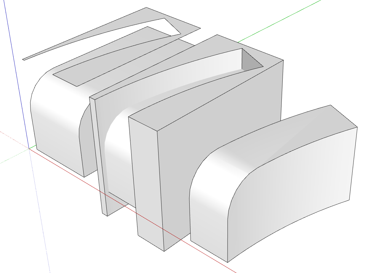
That's normal behavior for the method you are using. Easier approach to get the correct result would be to add the corner radius before cutting the large arcs.

All the Migrator does is copy the extensions from the Plugins folder of the older version and paste them into the new version. If you have outdated extensions, they may create errors when you start the new version of SketchUp again. As for the licensing of extentions, it depends on the extensions and how the licenses are managed. For extensions from SketchUcation, you should use the Sketchucation ExtensionStore to install your bundle of extensions. First install the latest version of the ExtensionStore. Doing that will ensure you get the latest versions of those extensions installed and that they will be installed correctly.
I needed to replace guides for the locking bars on some windows in the house. The OEM parts haven't been available for years so it was SketchUp and my 3D printer to the rescue.
An original that is close to neededing replacement.
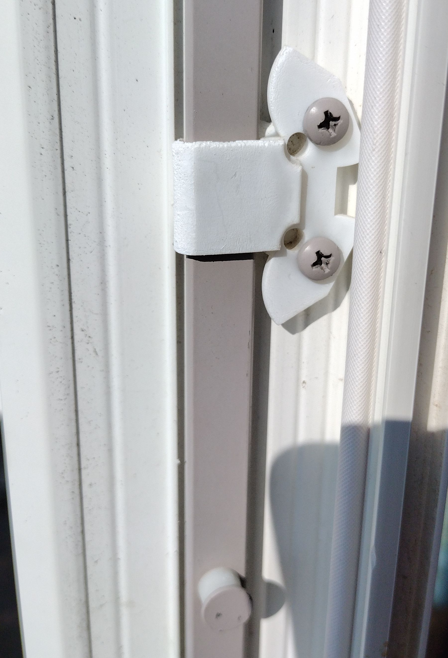
My SketchUp model. I couldn't see any practical reason for the curvy bits or the notch so I simplified it which also made it easier to print.
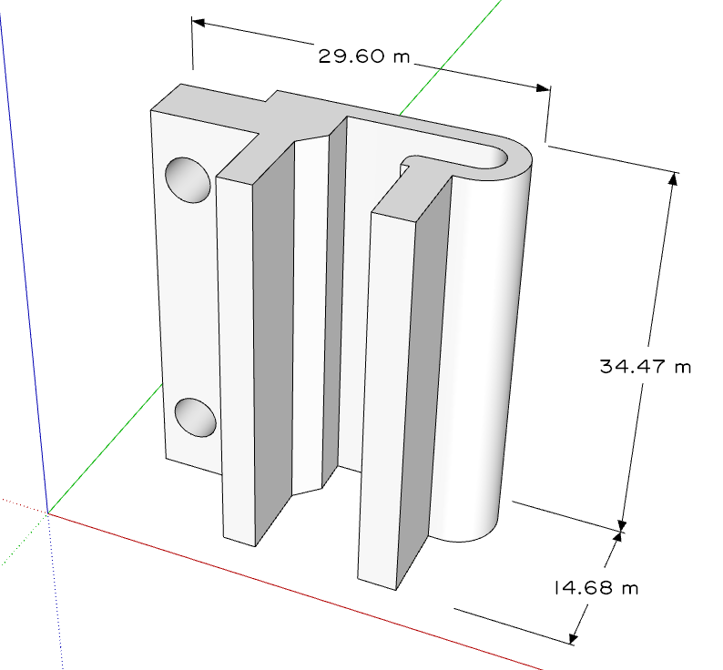
And the replacement installed.
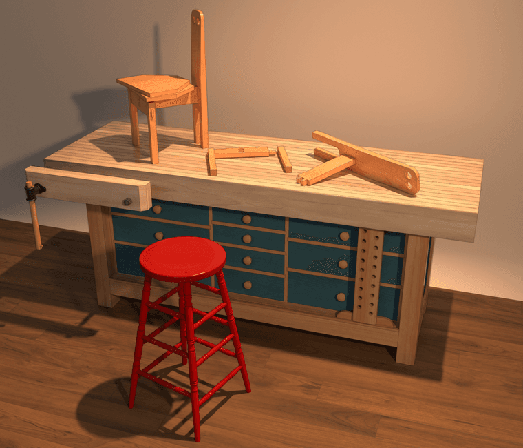
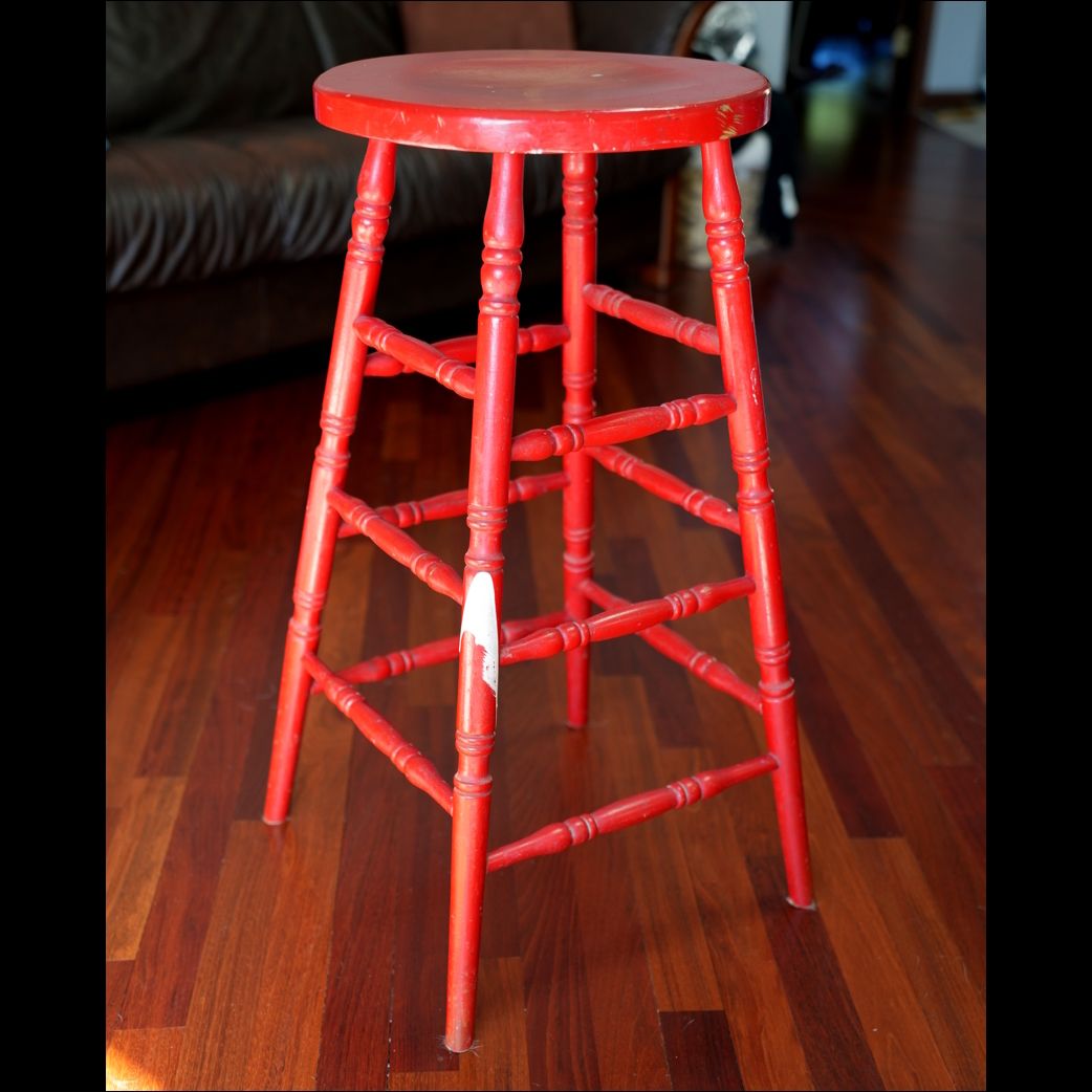
Not sure what took me so long but I finally modeled my grandfather's shop stool. The original is better than 65 years old. Brings back a lot of memories for me when I sit on it.
The original stool in its original paint.
The workbench is a Shaker-style bench I modeled for Fine Woodworking Magazine and the chairs are children's chairs designed by Dieter Gullert
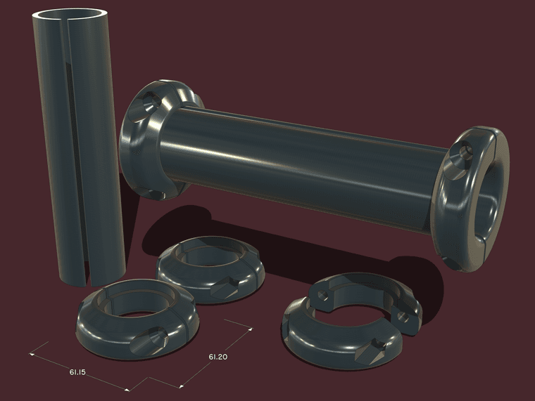
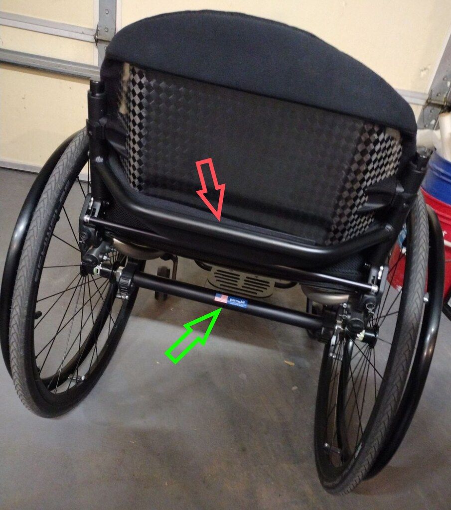
Another 3D printing project for a wheelchair. The tube was made of TPU and fits on the axle tube of a wheelchair to provide padding and protection from where a wheelchair lift picks the chair up. The rings clamp on either end of the tube and prevent the chair from shifting side to side. They were made of PETG.
The axle tube is indicated with the green arrow.
As Rich suggests, SPGears is a good option. If you can use standard bevel gears you might check manufacturers and suppliers for files you can use in SketchUp. For example I got a STEP file for the gear shown here from McMaster-Carr which I imported into SketchUp using the Universal Importer available in the ExtensionStore. The result can easily be modified for the shaft it needs to fit and so on.
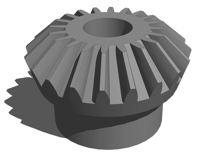
Since you are modeling for 3D printing, do the modeling in meters to avoid issues with tiny faces.
Couldn't help but do a little playing while avoiding work I should do.
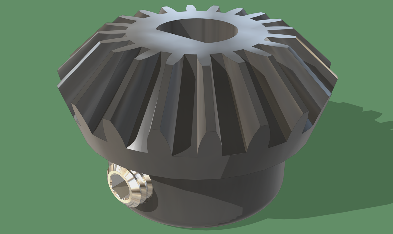
@Rich-O-Brien thank you sir! I was thinking it needs at least a few thumb prints.
FWIW, this image is from LayOut after adding the labels and the table which was made via SU's Report Generator. I combined the image export from LO with the image of the old paper. I could have added the old paper image directly into LayOut but I prefer keeping it separate so I have more flexibility in the final appearance. The following was done simply by changing the layer for the LO image to Overlay. Not perfect but for no more time than I have invested, it's acceptable.
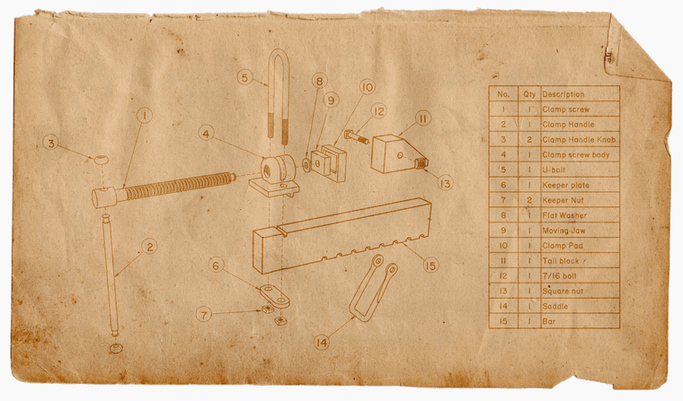
A project from my printer:
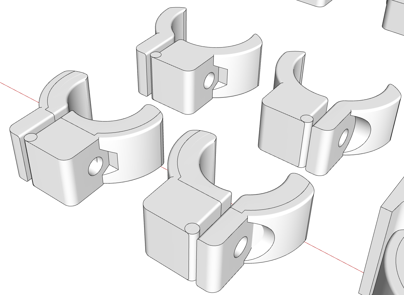
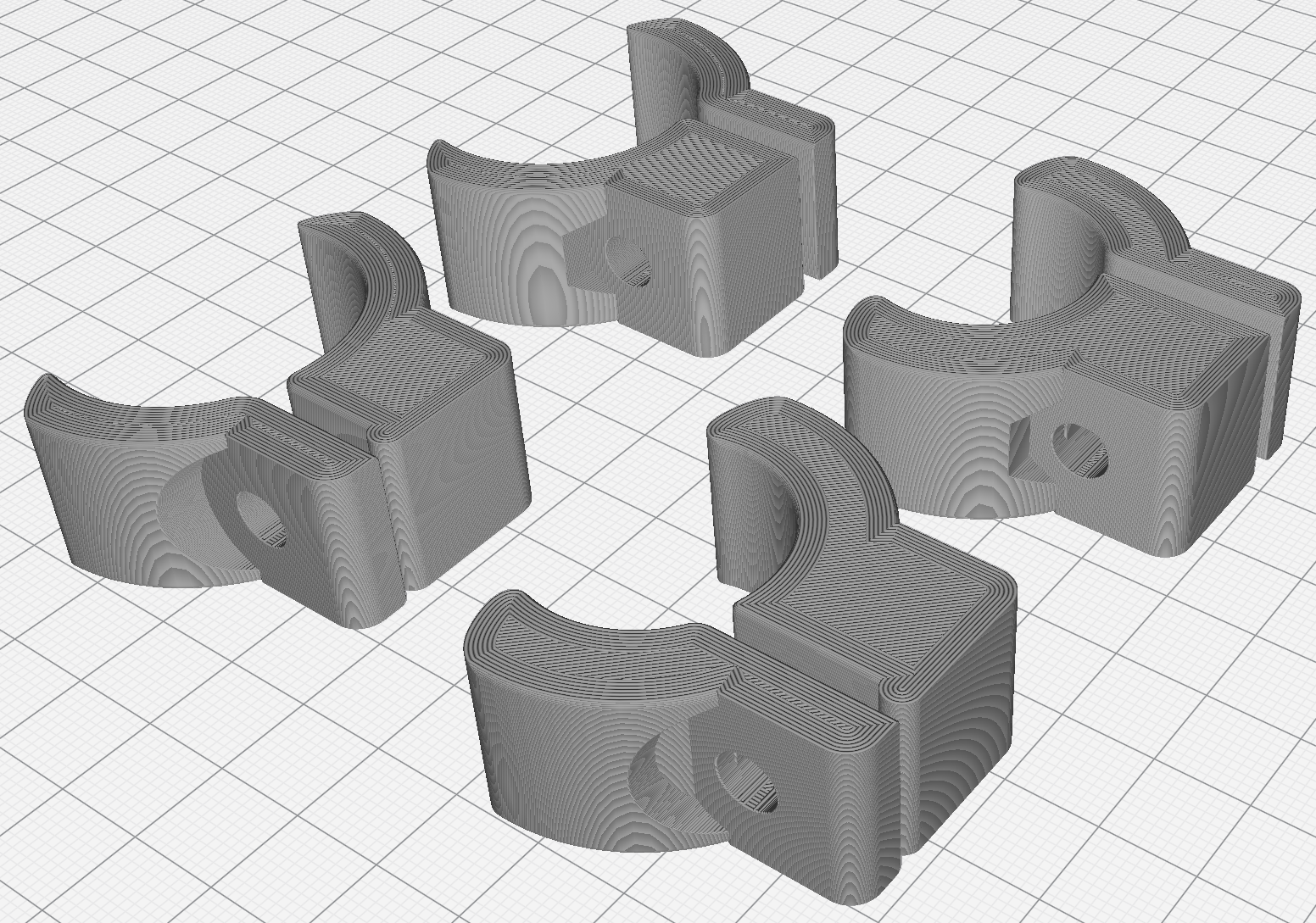
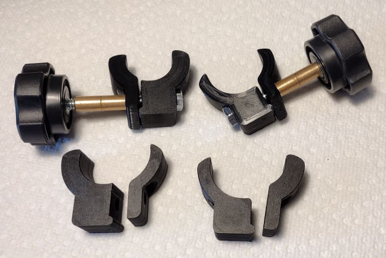
These are some clamps to go onto round tubes. There are two sets for two different sizes of tubing. The larger ones were modeled first. Rather make new ones for the smaller tube I just modeled a sort of filler as a separate solid. The original design didn't have the fulcrum (cylinder) but I added it, again as a separate solid. I decided not to merge them so that the clamps are easier to modify if needed.
I wasn't thrilled with the wire rope so I redid that this morning. 6x7 wire rope now.
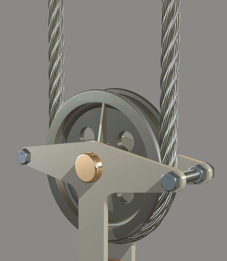
Really should be done with a texture but it's not.
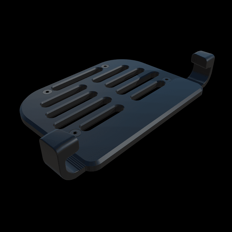
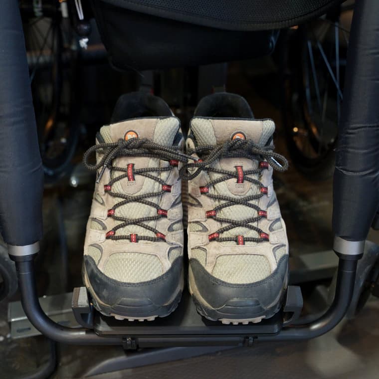
this is a simple thing from SU2025. Straight out of it with no editing. This is a footplate attachment for a wheelchair with adjustable guards or brackets on the side to help keep the user's feet on the plate.
You can't see much of it but here's the 3D printed version in place on the chair.
@Rich-O-Brien I agree with you regarding better renders. Vray and others will always have the edge. i don't see Trimble bloating SketchUp with a full-blown renderer. Their arrangement with Chaos Group for the Studio subscription makes better sense than including a full renderer in SketchUp from a development and management point of view, too.
Thank you for the compliments. This does work well for some of my presentations.
You and I have gotten a lot of use from Style Builder. My guess is most SketchUp users have never even opened it or know what it does. Seems the vast majority of users want to create photo-realistic images of their models and don't like the sketchy look. I plan to keep it around as long as I can and will still use it.
Another little steam engine. The flywheel has a diameter of 80mm. Nothing but SketchUp.
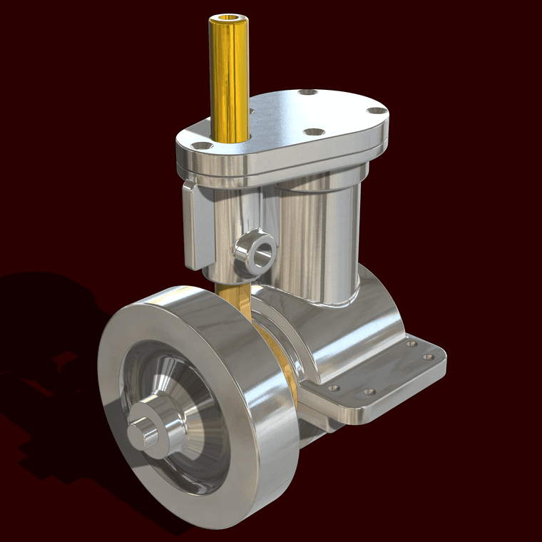

@tuna1957 thank you sir. I have been amazed at how many different little steam engine models I've found.
Not a steam engine this time. Instead this is a machinist's model of a shaper. The top part reciprocates forward and back pushing a cutter over the work clamped in the vise. As the machine cycles the table with the vise on it increments to the side after each stroke.
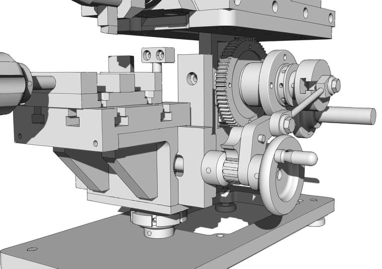
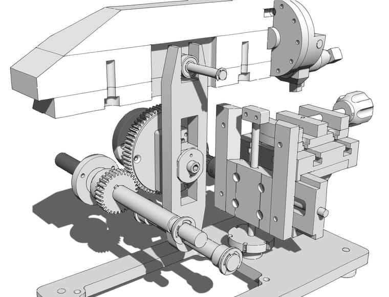
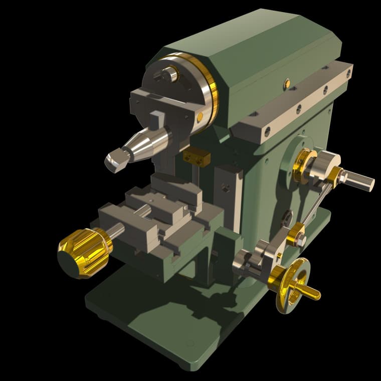
Still need some screws, nuts, bolts, and rivets but otherwise it's finished. Should even be timed correctly.