[Plugin][$] Curviloft 2.0a - 31 Mar 24 (Loft & Skinning)
-
Fredo I am a big fan of your work, i hang my head in shame and confess that i cannot get the Curvilot to work when i start uo SU i get the following message " Module Curviloft requires LibFredo6 version greater than 35. Current version is 34" but i do have Version 35 in the plugin dir as well as 34 if i remove the 34 many of my other Fredo plugins work is it possible for anyone to diagnose my problem?
Thanks in anticipation -
@grim said:
fredo and charly
this tool is fantastic, however after reviewing the examples posted by charly i was eager to try them out for myself but when it came time to try step 3 if found that the curviloft menue did not display the same information nor did the black backround profile menu appear i have sinced removed all rubies and reloaded only the latest from you posting to see if i had installed it incorrectly however i get the same responce
can you enlighten me as to the problem or is there somthing i am over looking
thanks
Maybe you just need to click on a junction to get the floating palette appear, if it is your problem.
Fredo
-
@dolphus said:
Fredo I am a big fan of your work, i hang my head in shame and confess that i cannot get the Curvilot to work when i start uo SU i get the following message " Module Curviloft requires LibFredo6 version greater than 35. Current version is 34" but i do have Version 35 in the plugin dir as well as 34 if i remove the 34 many of my other Fredo plugins work is it possible for anyone to diagnose my problem?
Thanks in anticipationCheck out if you have a subfolder named LIBFREDO6_Dir_35 in the Plugins directory. Normally, the script automatically select the latest version of LibFredo6
Fredo
-
fredo
thanks for the pointers, they work... there seems to be a lot more to using this tool than i realise, i am getting the hang of it slowly
-
Thank you for the quick reply, I thought i had put the folder in i have now and it works
Thank you very much -
@daniel s said:
Here I make another quick test for loft feature. It´s simple but y really want to know if it would work in this cases.
Daniel S
I missed this one.
Here is the result, with Loft by Spline
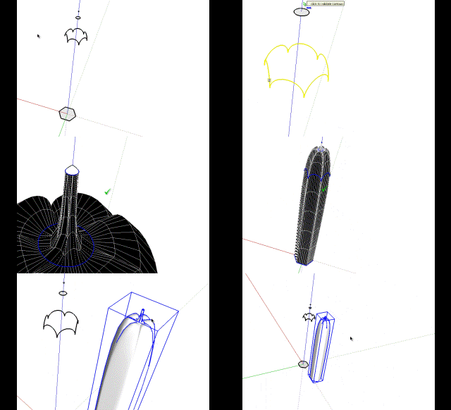
Fredo
-
danial
tried you shape file and came up with very different results see attached file
can you enlighten me as to where i am going wrong as i followed your instructions as well as trying one of my own
regards
david
-
You can select all the contours to make the loft:
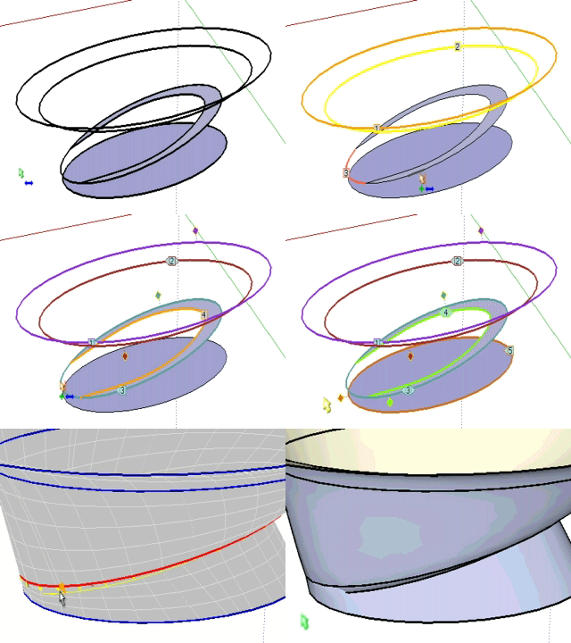
You will see that there is a problem with the default method.. try to change it with the toolbar for different results:
Or you can make it in two parts (for this model I wanted this result):
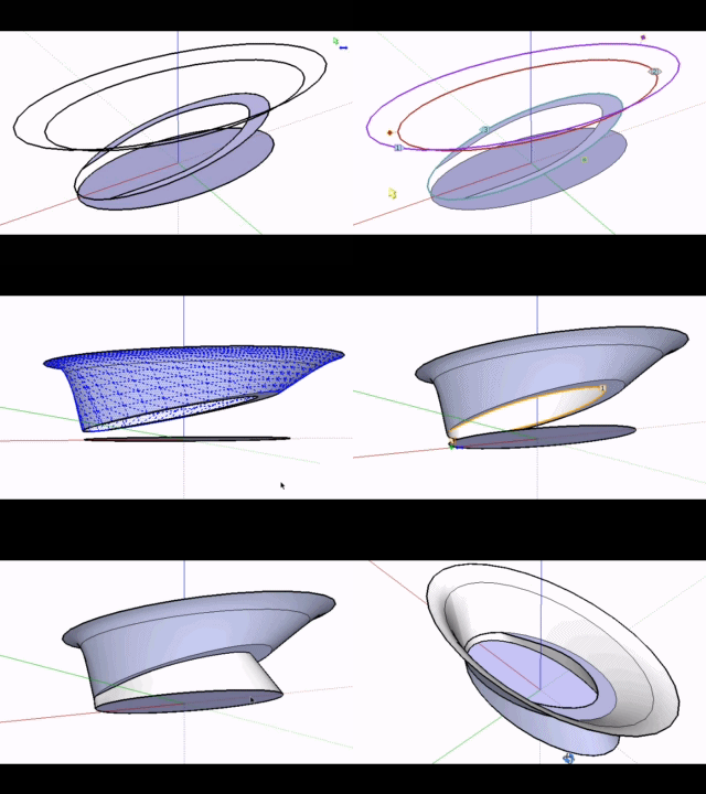
Daniel S
-
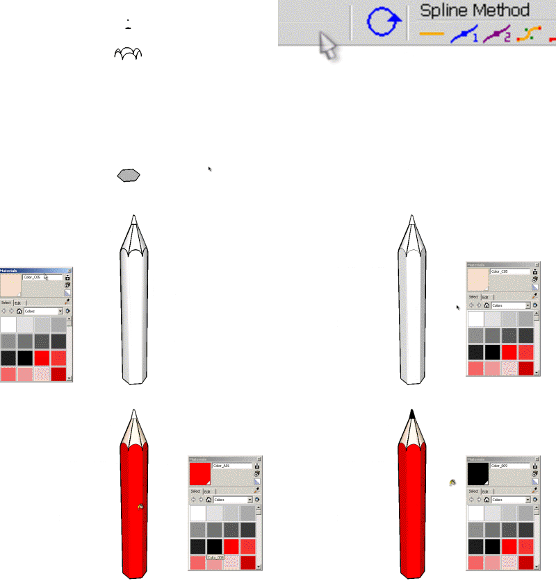
The idea was a result like this for that model:
Is better to make the loft in parts and not all togheter in a lot of cases.
For example, I´m making a shape where two contours share edges.
it is better to make a loft between 1-2-3, then explode and after that make the loft 4-5 for better results:
I attach the skp to show that if you make a loft of 1-2-3-4-5 the results are not good in this case.
Daniel S
-
@daniel s said:
The idea was a result like this for that model:
[attachment=6:fuxjwvvf]<!-- ia6 -->pencil.JPG<!-- ia6 -->[/attachment:fuxjwvvf]Daniel SFor the pencil, use the regular Bezier method (first method) instead of Cubic Bezier (default method).
[attachment=0:fuxjwvvf]<!-- ia0 -->Pencil Loft Daniel S.png<!-- ia0 -->[/attachment:fuxjwvvf]
FredoPS: for the other shape, there are still some issues when curves are partially overlapping. But it is a good example I can work from.
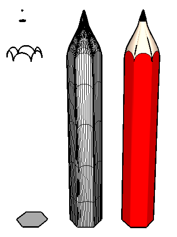
-
I've yet to try out this plugin for myself - but is there a linear option as well? Or is it just beziers? It seems to be that the pencil would require a linear morphing to get the shape of the tip.
-
@thomthom said:
I've yet to try out this plugin for myself - but is there a linear option as well? Or is it just beziers? It seems to be that the pencil would require a linear morphing to get the shape of the tip.
The Linear option will be available in the next release (along with other spline methods). I came to that conclusion too.
Fredo -
Just came across this wonderful and amazing new tool.
I'm pretty much speechless: incredible
This opens up soooo many possibilities. Thank you for this great tool
-
I haven't even had time to use it and I am already in love with this plugin.
Thanks Fredo -
-
Hi,
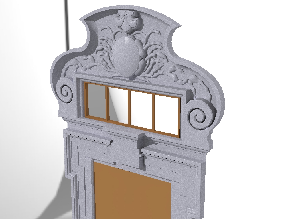
I tried with Curviloft the to make the ornaments in this historic door . But it does not look good. I have to try other shapes. In the rendered image it looks like a Crab.
-
@unknownuser said:
@thomthom said:
I've yet to try out this plugin for myself - but is there a linear option as well? Or is it just beziers? It seems to be that the pencil would require a linear morphing to get the shape of the tip.
The Linear option will be available in the next release (along with other spline methods). I came to that conclusion too.
[attachment=0:12mbvobp]<!-- ia0 -->Pencil for Loft - Daniel S - linear.gif<!-- ia0 -->[/attachment:12mbvobp]
FredoYou cannot stop amaze! This already is a true gem. Wonder to what it will grow...
-
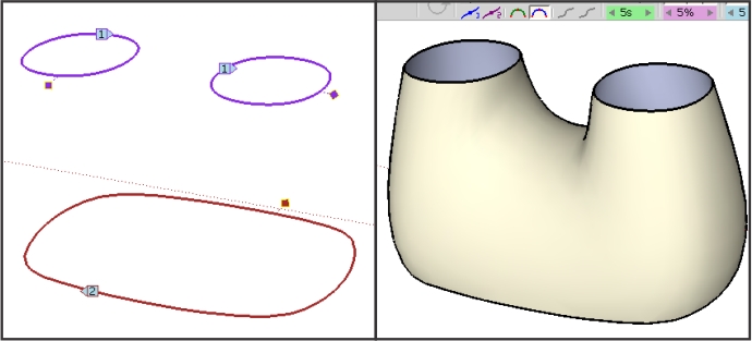
I just see:
http://forums.sketchucation.com/viewtopic.php?f=18&t=29374#p256698
And made me wonder... would be possible something like this?
Daniel S -
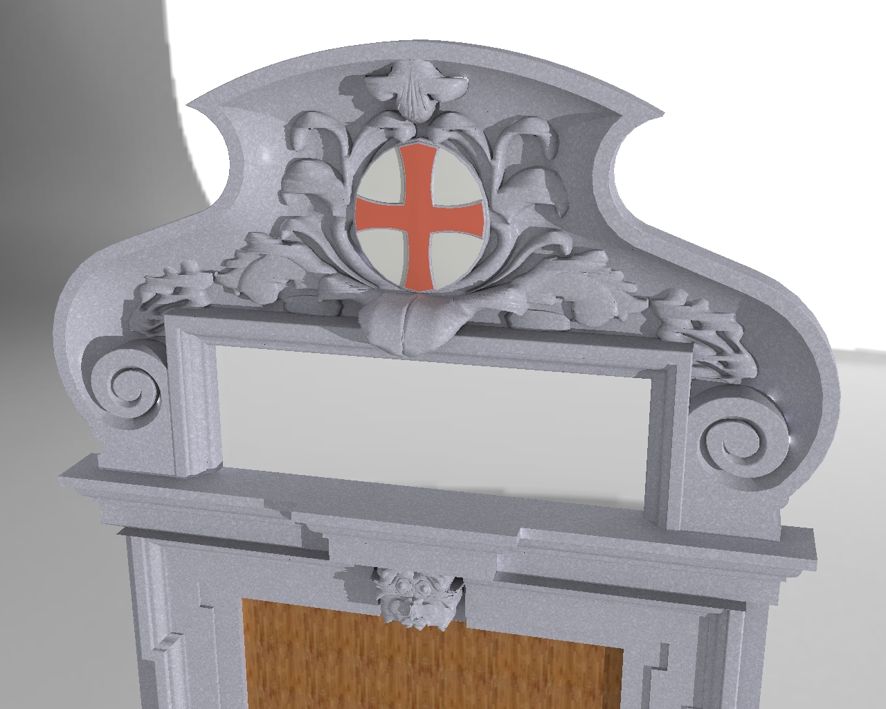
I have further experimented with Curivloft. But for those stone sculptures, it seems to be less suitable. The current forms I have generated by the standard tools, the Freehand tool, Push Pull and Subdivide and Smooth.
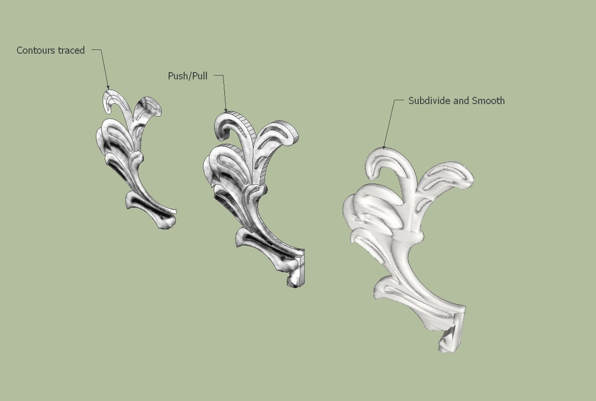
-
Notice that the numbers for each profile alternates throughout your pre-selecting.
Advertisement


