sketchucation logo sketchucation
    • Login
    1. Home
    2. TaffGoch
    3. Posts
    Oops, your profile's looking a bit empty! To help us tailor your experience, please fill in key details like your SketchUp version, skill level, operating system, and more. Update and save your info on your profile page today!
    πŸ”Œ Easy Offset | Offset selected faces in SketchUp in positive and negative offsets. Download
    Offline
    • Profile
    • Following 0
    • Followers 0
    • Topics 7
    • Posts 364
    • Groups 1

    Posts

    Recent Best Controversial
    • RE: Space frame ? [TUTORIAL]

      Jacob,

      How are you getting along with the Senster?

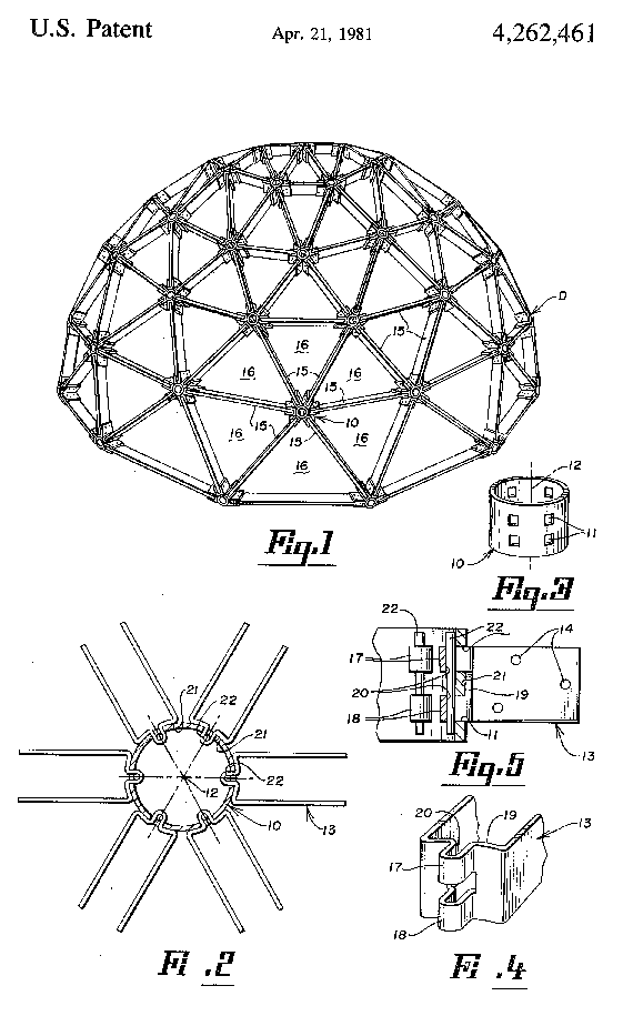
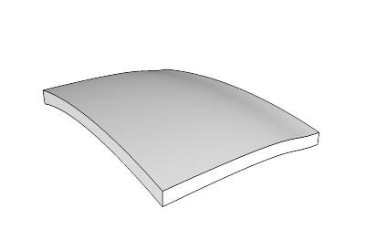
      The above guidance should provide a very good start. I wouldn't worry about tubes and hydraulic cylinders, until you've got the overall geometry (as polyhedral "blocks") pretty well sussed out. Only after you've got the building blocks sized and scaled to look about right, do you proceed to add detail. Tubes, angle-iron and actuators can be added, as components, after you have completed the basic polyhedral blocks, which can be used as a 3D template, upon which to build.

      If you try to add detail, before you've got the overall geometry established, you're going to have problems making changes to the underlying "block" skeleton. Get the polyhedron blocks right, first. Don't worry too much about exact dimensions, as the relative scale of each block, compared to it's connected blocks, is more important. Once you've finished the model, you can scale the whole thing, to somewhat match the photographs. (Really, who is going to know that your dimensions are off a bit?)

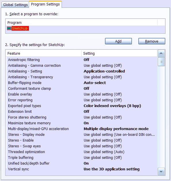
      When adding & positioning tubing components, rotating around specific axes, or aligned to particular faces, is a SketchUp skill you need to master. See the SketchUp Users Guide, "Folding Along an Axis of Rotation" Β It's applicable to any rotation, not just "folding." Once you've mastered such rotations, precise positioning is a snap (literally.)

      Actually, you've "...flung a cravin' on me!" Β I'm considering trying my hand at modeling the Senster, myself.

      Taff


      Senster_hand.skp


      Senster_hand.png


      senster9.jpg


      Senster-scale.jpg


      DSC00018.jpg

      posted in Newbie Forum
      TaffGochT
      TaffGoch
    • RE: Dome with smooth edges

      Hello, all,

      I've been "lurking" on this discussion, and see that Al has posted an image of Simon Thomas' sculpture, "Orb"...

      http://plus.maths.org/issue8/features/art/orb.jpg

      As Gaieus mentioned, it is, indeed, based on a geodesic sphere (class-I, frequency-2, if you're familiar with the terminology.)

      Several other of Thomas' sculptures are compelling, and would make for interesting SketchUp exercises.

      http://plus.maths.org/issue8/features/art/hc4.jpg

      http://plus.maths.org/issue8/features/art/hcone1.jpg

      See here, for descriptions: The art of numbers


      For geodesic design in SketchUp, I often use an online java applet that can output a text file of the x,y,z coordinates for each vertex, which I then import into SketchUp, as a "point cloud"...
      Thomson Problem

      ...just another (powerful) geodesic resource, should you be looking for such.

      Taff

      posted in Newbie Forum
      TaffGochT
      TaffGoch
    • RE: How to draw a Dome in Sketchup... Not Bowl

      @gaieus said:

      This is his "obsession" if you want to put this way πŸ˜†

      Guilty as charged -- Although I prefer "enamoured" πŸ˜‰
      Google Groups profile: TaffGoch

      (Nstocks has now posted at the Geodesic Help Group, but that shouldn't exclude you all from continuing to reply with your help and experience.)

      Taff

      posted in SketchUp Discussions
      TaffGochT
      TaffGoch
    • RE: Bad News for Architects in the next ver. of Google Sketchup

      Anyone have experience(s) with AutoDesk's "FBX" converter?

      http://usa.autodesk.com/adsk/servlet/index?siteID=123112&id=8224926
      http://area.autodesk.com/fbx
      http://images.autodesk.com/adsk/files/autodesk-fbx-converter-guide.pdf

      While there's an AutoCAD plugin, the "FBX Coverter" is a standalone program (free download) that reportedly has COLLADA and DXF conversion capabilities (import & export.)

      posted in SketchUp Discussions
      TaffGochT
      TaffGoch
    • RE: Latest Work with Curved Roof Design

      xrok1,

      Those tiger-grain oak struts should provide for a very impressive (and expensive) ceiling !
      πŸ˜„

      posted in Corner Bar
      TaffGochT
      TaffGoch
    • RE: Latest Work with Curved Roof Design

      Fred,

      Further simplification, using thinner galvanized plate (the same stuff of which joist hangers are made.)
      Bracket/hanger
      The bolt can be more-simply replaced with a long clevis-pin, making assembly much easier/faster (possibly cheaper, too.)
      Clevis pin
      This is pretty close to your original connector design, and can be bent, using a jig and hydraulic press (jack) or vise & hammer. Since it's made of "plate" material, it doesn't have to be as thick as the straps in my first model. Additionally, it permits a more intimate strut-to-pipe fit.

      Taff


      Bracket & bolt

      posted in Corner Bar
      TaffGochT
      TaffGoch
    • RE: Latest Work with Curved Roof Design

      Fred,

      If you're going to model with the connector I modeled, you should move the two stut "u-straps" as far up, and as far down, as possible. I modeled them in more central positions, to ensure that they wouldn't interfere with skinning.

      The bottom strap can probably be (would best be) moved all the way down, without ever having to be subsequently moved.

      The top strap should be positioned as high as possible, without "poking" above the top surface of the strut.

      A "shorter" hub pipe would permit central positioning on the end of the strut, with the strut-straps at the top-most and bottom-most positions, all the time.


      I'm thinking tension forces, not compression forces. Compression would push the strut against the hub, and all's okay. Tension, however, would pull the strut away from the hub. If the strut U-straps are more-centrally located, the hub-strap could bend. If the strut straps are positioned at the extreme upper/lower locations, bending of the hub-strap should be ruled out.

      (I would have modeled that way, had I thought of the tension-force potential earlier.)

      Taff

      posted in Corner Bar
      TaffGochT
      TaffGoch
    • RE: Latest Work with Curved Roof Design

      Fred,

      This connector is composed of 3 pieces of "strap" steel stock, requiring only bending and drilling (no casting.) All connectors are identical, with no custom angle restrictions.

      (A modification of one of the patent connectors, to make DIY easier, with no welding, although it can be welded, if desired.)

      The wood struts are connected to the straps first, using wood screws in the ends, and bolts all the way through the faces. Final assembly is completed by positioning on the hub pipe, and inserting the long hub bolts.


      Strap connector


      SketchUp6 model file format

      posted in Corner Bar
      TaffGochT
      TaffGoch
    • RE: Latest Work with Curved Roof Design

      @fbartels said:

      I tried to contact Woods to see if he still had any kits for sale, or would just be willing to have a conversation. I never heard back from him.

      Well, Dyna Domes has been out-of-business for some time now. Last I heard (Dec 2008,) Bill Woods was retired, in Buckeye, Arizona.

      posted in Corner Bar
      TaffGochT
      TaffGoch
    • RE: Latest Work with Curved Roof Design

      Here's another of Shuhei's "bubbletecture" projects:
      http://www.designboom.com/weblog/cat/9/view/5299/bubbletecture-m-maihara-kindergarten-by-shuhei-endo.html

      In Google Search, "bubbletecture" reveals much of his work.

      Taff

      posted in Corner Bar
      TaffGochT
      TaffGoch
    • RE: Latest Work with Curved Roof Design

      @earthmover said:

      TaffGoch...that is a really amazing structure. Did it start as a sketchup design?

      I know next-to-nothing about the design tools employed by the Japanese architect, Endo Shuhei. I first read of his "bubbletecture" here:
      http://www.inhabitat.com/2008/10/16/bubbletecture-h-by-shuhei-endo/

      Note that, while most of the roof is steel, part is covered by moss. (Reminds me of Fred's "green" free-form roofs.)

      Taff

      posted in Corner Bar
      TaffGochT
      TaffGoch
    • RE: Latest Work with Curved Roof Design

      I knew I had a picture of the Billy Woods hub (patent 3486278) that depicts the hub better than the line drawing.
      DynaDome hub 1970.jpg
      Billy Woods was the originator of the "Dyna Domes" company, and was featured in LIFE magazine.

      I see that he, and Dyna Domes, were mentioned in your previous posts in the Woodworking discussion:
      http://forums.sketchucation.com/viewtopic.php?f=183&t=17745

      I wasn't sure you had previously seen this particular photo.

      Taff

      posted in Corner Bar
      TaffGochT
      TaffGoch
    • RE: Latest Work with Curved Roof Design

      Fred,

      I suspect you'll like this...


      bubbletecture7.jpg


      en4.jpg


      en2.jpg


      en5.jpg


      en3.jpg


      bubbletecture1.jpg

      posted in Corner Bar
      TaffGochT
      TaffGoch
    • RE: Latest Work with Curved Roof Design

      Hey, Fred,

      You know that such a topic is right down my alley!

      There are a few "universal" connector designs for geodesic domes that I like. Here's one:
      Geodesic_connector.png
      The patent reference for that one is:
      http://books.google.com/patents/about?id=dR1AAAAAEBAJ

      You get more-than-a-few hits for "geodesic" and "hub" or "connector" from the Google Patent Search engine:
      http://books.google.com/patents?q=geodesic+connector
      http://books.google.com/patents?q=geodesic+hub

      Personally, I really like this one:
      Patent_4464073_hub.png

      This one somewhat combines the two:
      Patent_4262461.png

      This one requires more work, and can probably be simplified further. It's specifically designed to use on a hub made of a section of pipe:
      Patent_4365910.png


      I invite you to download a copy of "Domebook 2," following the link provided here:
      http://groups.google.com/group/geodesichelp/browse_thread/thread/51760c3c225ffd66

      There's plenty of "prior work" out there for you to reference.

      I like your free-form application of geodesic-like construction. Note that, when construction-glue and screws are used to attach the plywood to the struts, the unified "skin"-and-struts provide most the primary strength for such a roof. The hubs keep things aligned, during and after construction, but don't carry as much of the stress-load after gluing-up the "skin."

      Regards,
      Taff

      posted in Corner Bar
      TaffGochT
      TaffGoch
    • RE: Sketchup preset for the NVIDIA Quadro 1700

      @pep75 said:

      Does anyone have a good preset for a Quadro 1700 card that I can load into the NVIDIA control. I'm not so satisfied about the card and I wonder if this is a software issue(setting) or a hardware issue.

      Pep,

      I have the Quadro FX 1500M, and use the nVidia-customized driver. The SketchUp developers and nVidia partnered together to produce the customized settings. This screen grab is of the nVidia control panel, outside of SketchUp:
      nVidia-Quadro-SketchUp-sett.png
      I noticed improved speed, and correction of anti-aliasing and backface-shading issues.

      I don't know if the 1700 uses the same driver, but its control panel should allow you to customize the settings yourself, following the settings depicted in the above image.

      Taff


      SketchUp Pro / Version 6.4.112
      SketchUp Pro / Version 7.0.8657
      Windows XP Pro / SP3
      DELL Precision M90 / 2 GB RAM
      nVidia Quadro FX 1500M / 256 MB
      nVidia driver: Forceware 169.96

      posted in SketchUp Discussions
      TaffGochT
      TaffGoch
    • RE: How about an 'Honour Board' here???

      @gaieus said:

      "I now forget what exactly I used [a]s search terms, and where I ended up."

      Hmmm, might it have been here, where you "ended up"?
      http://avatar.pho.to/

      TaffGoch.gif

      posted in Corner Bar
      TaffGochT
      TaffGoch
    • RE: Chair back curved both vertically and horizontally

      gull,
      Depending on the uniformity of the curves, you may be able to produce your chair back by following the methodology demonstrated in NoelD's help model, available at the 3D Warehouse:
      http://sketchup.google.com/3dwarehouse/details?mid=4b2c9f11f5dba3b0a84af70808174cdc

      Taff


      download1.jpg

      posted in Newbie Forum
      TaffGochT
      TaffGoch
    • RE: How to create curved stair

      @moghamdi said:

      ...please can you explain how you made the last step??

      Mohammed,

      Draw new diagonal line entities from the bottom corner of each step, to the next bottom corner. When done, you can select the new lines, and copy them downward by your desired amount. This will provide the bottom curved line, from the first floor to the second.

      Note that I used groups. If you employ the above description while 'inside' the edit of the group, you have to use the copy feature of the move tool, then delete the original curve.

      If, however, you keep the group closed, and draw your new diagonals on the 'outside' of the group, the lines won't 'stick' to the group geometry (but inferencing still works.) You can then move the new curved line downwards, without distorting (dragging) the geometry within the group. Once you have the diagonal curve in the new position, select the complete curve and use <ctrl-x> to delete it. This will delete and copy the entities onto the clipboard.

      Immediately open the group for editing, and use "Paste-in-place" (Edit menu) to insert the 'deleted' curve into the group's geometry. The rest is cleanup and hand-stitching the underside. (You can use the 'Skin' plugin instead of hand-stitching.)

      EDIT: See several posts down, for clarification regarding the rounded steps having two lines defining the outer edge. To draw the diagonals, this middle point has to be included, as well. xrok1 describes one method. [Sun Feb 15, 2009 5:20 pm]

      Taff

      posted in Newbie Forum
      TaffGochT
      TaffGoch
    • RE: How to create curved stair

      Ooh, sorry about that...

      You're right -- I had added an additional endpoint to make the step outer edge 'curved,' instead of straight.

      The steps xrok1 describes work well. I actually drew a vertical line from each step 'middle' point, straight down (using the <up> arrow key to limit the line to the 'blue' axis,) and using the midpoint of the vertical edge of the step to set the length of the line. This, essentially, provides the same results as xrok1's method. (You could probably come up with several similar tricks to achieve the same objective.)

      Good catch, xrok1. Sorry for the oversight, Peter.

      Taff

      posted in Newbie Forum
      TaffGochT
      TaffGoch
    • RE: How to create curved stair

      I drew several step edges by eye, to identify the approximate location. I then drew a 'point at intersection' (using the plugin of that name.) After erasing the original 'by eye' edges, keeping one, I rotate/copied that edge, using the array-copy feature of the rotate tool.

      If you draw the first edge, then rotate/copy to the last edge position, you can use the rotational array feature of the rotate tool to fill in all the others in between (using the divide symbol in the VCB.) Since twelve steps appear to be rotated in equal increments, type "/12" in the VCB and hit <enter>. This is described in the SketchUp Users Guide, under "Creating Multiple Copies (Radial Arrays)"

      All the centerpoints were developed in the same manner -- by eye, then adjusting position until adequate for drawing the correct circle. If the centerpoint wouldn't provide a circle in the correct location, I shifted the centerpoint and circle by smaller-and-smaller increments, until a circle would develop where I needed it (i.e.; trial-and-error experimentation.)

      Taff

      posted in Newbie Forum
      TaffGochT
      TaffGoch
    • 1 / 1