Latest Work with Curved Roof Design
-
I made some good progress this summer with developing a framing system for highly-curved roofs. (The Savill Building provides a nice example of the type of curved roof shapes I would like to create.)
The progress came when I put aside the hexagonal hub connector system I'd been developing -with help from a number of folks here- and started exploring the use of PVC pipe for hubs. I chose a pipe shape for hubs because some exploration of curved space-frame structures like those in the two images below showed how strong these structures can be if you give them some depth via two layers and connections between them.
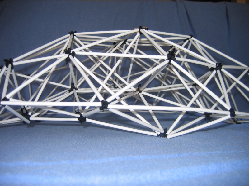
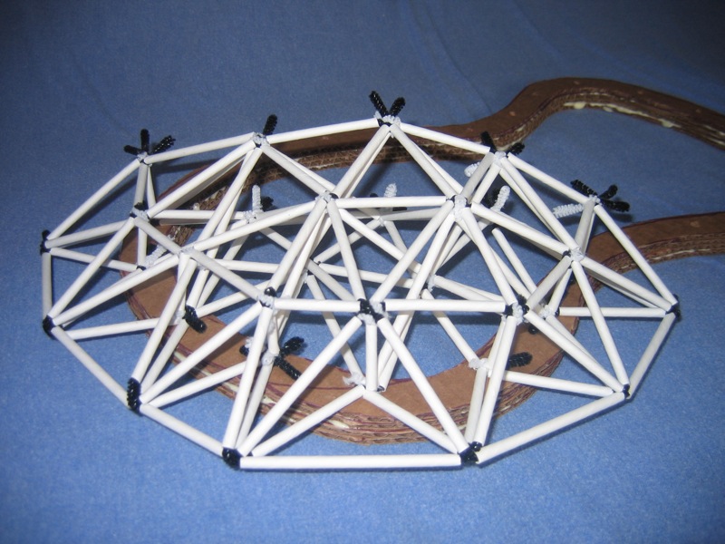
Once I understood the importance of depth to provide strength, some SketchUp modeling showed that a sytem of beams between vertical tubular hubs would be relatively easy to create with the tools at my disposal, along with SketchUp to provide the dimensions. (Note, in the first image below I had not yet come up with the tube-as-hub approach.)
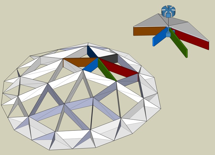
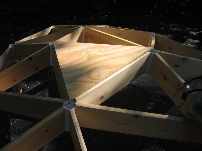
Using this approach I built the triangular grid shell stucture shown in the images below. The structure is very strong, as the photo of my lovely trusting wife standing on top attests. (I did, with my 200+ pound weight, test it first.)
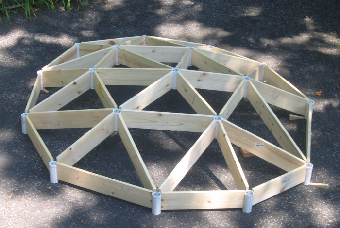
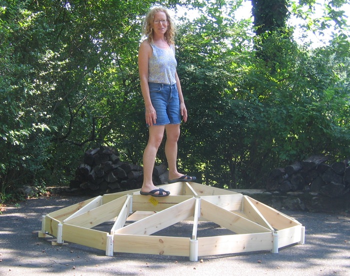
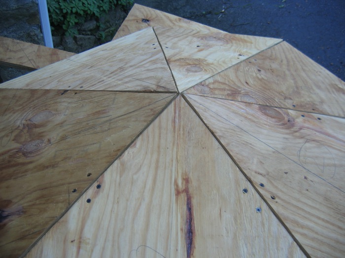
To finish off the structure I will attach triangular pieces of plywood to the framing. I've done some experimentation with this, as shown in the image below, and it should work just fine.
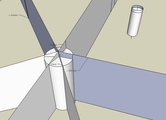
I'm now working on trying to improve the hub component of the system and could use some help from members of this community. A fair amount of searching has not uncovered any existing product designed to hang beams/joists from pipes. Do any of you know of products that provide this function? The next set of images (and the attached SketchUp file) should make clear the shape of the component.
Top view of a set of the proposed hangers.
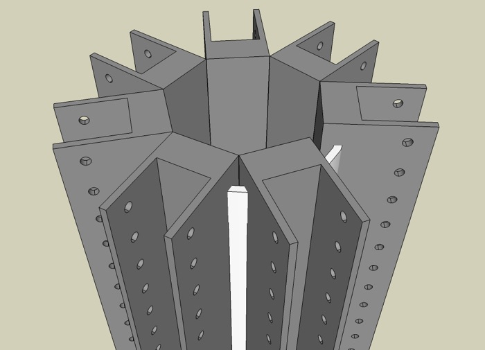
Bottom view of one hanger.
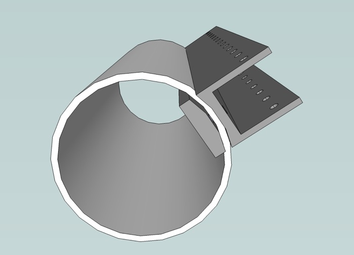
I've attached the SketchUp model of the grid shell structure for anyone interested.
Sorry about the long post but there was a lot to cover.
Fred
-
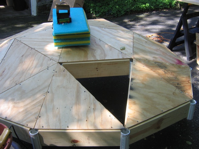
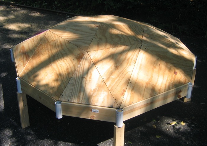
With lots of help from my son Robin we finished cutting and attaching the triangles to the roof frame yesterday. The approach I'd figured out for cutting the triangles worked beautifully. It is tedious but it creates triangles that fit perfectly on their triangular frames. OK, not perfectly, but well within the tolerances needed. Following are three images. One taken at the start, one with just one triangle left, and one with all the triangles attached.
If I were to make more of these I would want a better solution for the hubs. My current thinking is that short sections of steel pipe would be a good replacement for the PVC pipe sections. However, to use steel pipe some sort of joist hanger is needed to hang the beams from the pipe. If you happen to know of any such product please send along the information. Thanks. Fred
-
Not sure of the loads involved, but this might work, if you could find a simple way to connect them to the pipe. The advantage would be the ability to bend it to any angle.
Simpson will also make custom connectors, for a price
Tom
-
Interesting work my friend. Reminds of the geodesic greenhouse I built out in Washington state a few years ago. I've studied quite a bit about Fuller and geodesic principles and worked also at creating a proper hub system.
I found a few links regarding dome hubs that may be inspiring to you -
http://www.oldmoldy.com/Geodesic_Domes.php?aa=0&si0=0

Make your own 3v geodesic dome hubs
Geo-Dome: Making hubs is not easy but this article will gie you the basics in DIY domes category.
(www.geo-dome.co.uk)
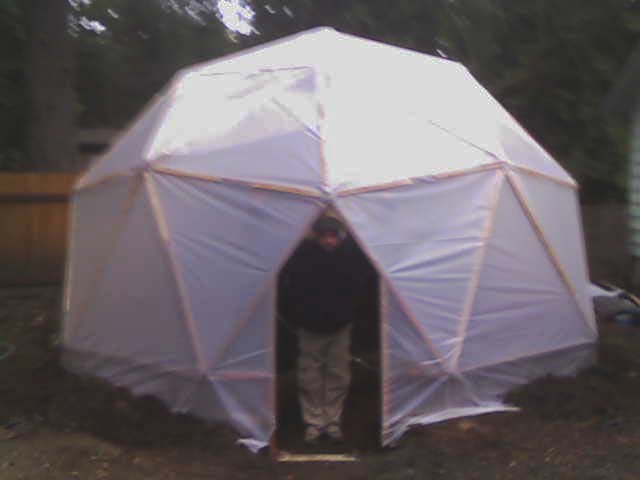
Below is a (rather blurry) pic of the dome we constructed for growing vegetables in the winter.
-
EarthMover, Thanks for the links. Given the irregularly curved roofing shapes I want to create, the fixed angles of traditional geodesic dome connectors will not work. Every triangle, and every hub, on the project above has unique angles.
How did the greenhouse geodesic dome work out?
Fred
-
Hey, Fred,
You know that such a topic is right down my alley!
There are a few "universal" connector designs for geodesic domes that I like. Here's one:
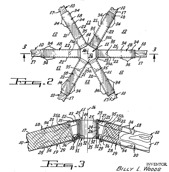
The patent reference for that one is:
http://books.google.com/patents/about?id=dR1AAAAAEBAJYou get more-than-a-few hits for "geodesic" and "hub" or "connector" from the Google Patent Search engine:
http://books.google.com/patents?q=geodesic+connector
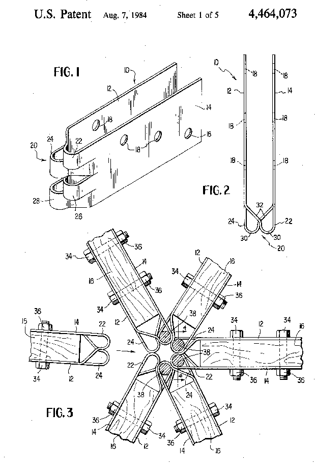
http://books.google.com/patents?q=geodesic+hubPersonally, I really like this one:
This one somewhat combines the two:
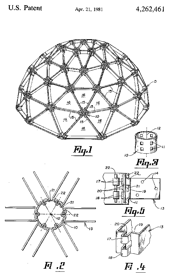
This one requires more work, and can probably be simplified further. It's specifically designed to use on a hub made of a section of pipe:
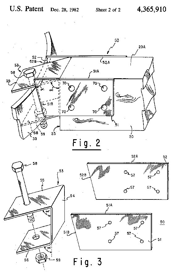
I invite you to download a copy of "Domebook 2," following the link provided here:
http://groups.google.com/group/geodesichelp/browse_thread/thread/51760c3c225ffd66There's plenty of "prior work" out there for you to reference.
I like your free-form application of geodesic-like construction. Note that, when construction-glue and screws are used to attach the plywood to the struts, the unified "skin"-and-struts provide most the primary strength for such a roof. The hubs keep things aligned, during and after construction, but don't carry as much of the stress-load after gluing-up the "skin."
Regards,
Taff -
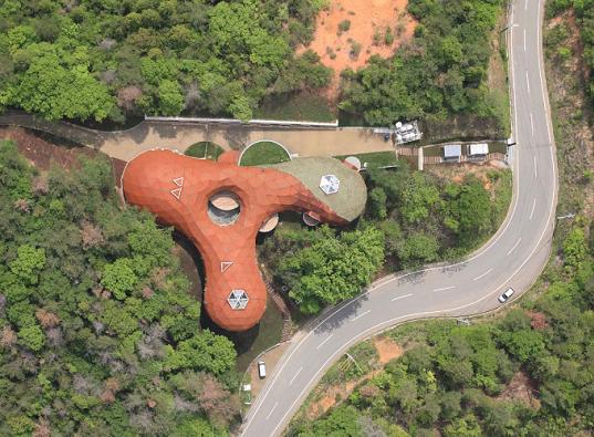
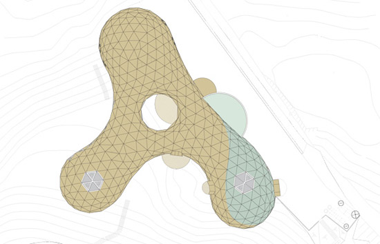
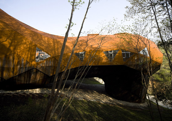
Fred,
I suspect you'll like this...
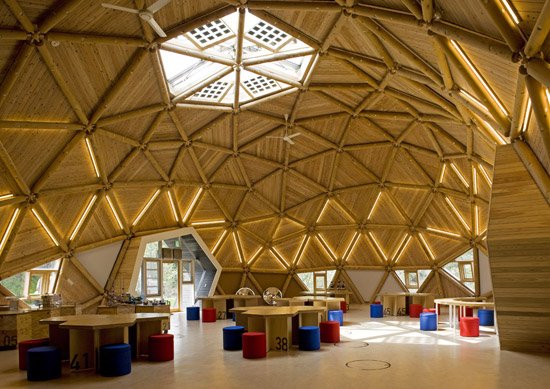
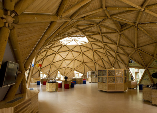
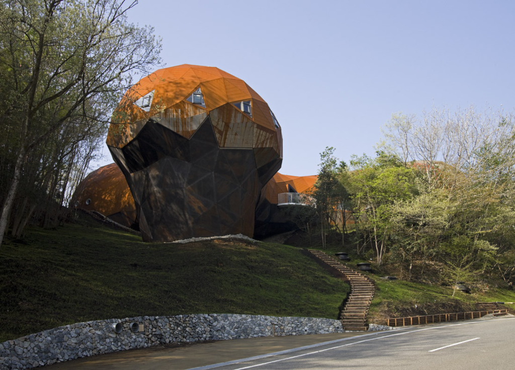
-
TaffGoch...that is a really amazing structure. Did it start as a sketchup design?
Fred, the greenhouse worked out well. I flew out to WA to construct it for a friend who was having some financial trouble. It allowed him to eat through the winter. He's since moved to Oregon and last I heard the dome was being used by it's new owner to grow medicinal marijuana. LOL
-
I knew I had a picture of the Billy Woods hub (patent 3486278) that depicts the hub better than the line drawing.
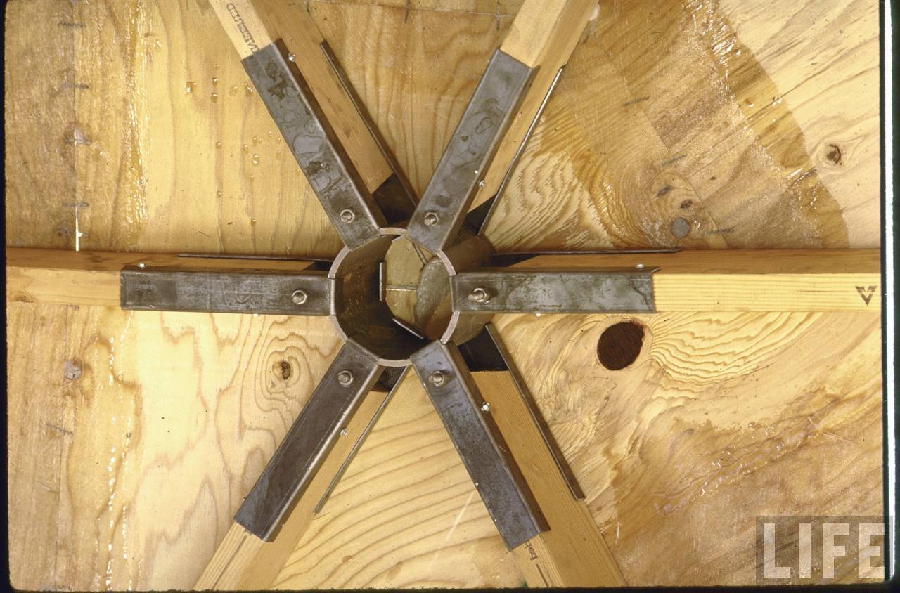
Billy Woods was the originator of the "Dyna Domes" company, and was featured in LIFE magazine.I see that he, and Dyna Domes, were mentioned in your previous posts in the Woodworking discussion:
http://forums.sketchucation.com/viewtopic.php?f=183&t=17745I wasn't sure you had previously seen this particular photo.
Taff
-
@earthmover said:
TaffGoch...that is a really amazing structure. Did it start as a sketchup design?
I know next-to-nothing about the design tools employed by the Japanese architect, Endo Shuhei. I first read of his "bubbletecture" here:
http://www.inhabitat.com/2008/10/16/bubbletecture-h-by-shuhei-endo/Note that, while most of the roof is steel, part is covered by moss. (Reminds me of Fred's "green" free-form roofs.)
Taff
-
Here's another of Shuhei's "bubbletecture" projects:
http://www.designboom.com/weblog/cat/9/view/5299/bubbletecture-m-maihara-kindergarten-by-shuhei-endo.htmlIn Google Search, "bubbletecture" reveals much of his work.
Taff
-
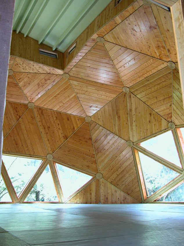
New Zeeland Aikido Dojo inspired by Bucky. Thing is that we still have to walk on horizontal surfaces

-
Taff,
Wow! Thanks so much for the links. Endo Shuhei's structures are the closest thing I've seen to what I'm trying to build in terms of his use of irregular triangles. I'd love to know more about the hubs in the two buildings you linked to. From the pictures it looks like he used different approaches in each building. I'm honestly not terribly thrilled with the exteriors of either building but the interiors are stunning.
Regarding Billy Woods hub design. I tried to contact Woods to see if he still had any kits for sale, or would just be willing to have a conversation. I never heard back from him. I definitely like his approach though. One big difference in my version is that all the hub pipes are vertical. This is possible because I'm working toward curved roofs, not domes. Using all vertical hubs solves a number of problems, including making it much easier to connect the roof to vertical walls.
Taff, I was pretty impressed with how strong the framing was without the skin. The plywood has tightened everything up, but the framing itself has its own structural integrity. I think it goes back to triangles being inherently undeformable shapes.
Anyway, thanks again for all the links. I've downloaded the Domebook 2 pdf and will peruse over the next week.
The help provided on this forum never ceases to amaze.
Fred
-
to amaze me¡
Thanks Fred -
@fbartels said:
I tried to contact Woods to see if he still had any kits for sale, or would just be willing to have a conversation. I never heard back from him.
Well, Dyna Domes has been out-of-business for some time now. Last I heard (Dec 2008,) Bill Woods was retired, in Buckeye, Arizona.
-
Fred,
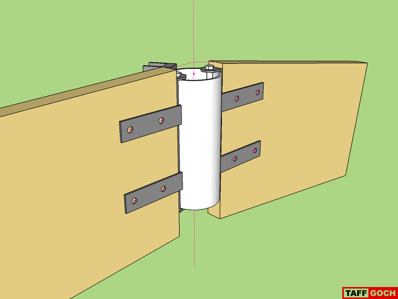
This connector is composed of 3 pieces of "strap" steel stock, requiring only bending and drilling (no casting.) All connectors are identical, with no custom angle restrictions.
(A modification of one of the patent connectors, to make DIY easier, with no welding, although it can be welded, if desired.)
The wood struts are connected to the straps first, using wood screws in the ends, and bolts all the way through the faces. Final assembly is completed by positioning on the hub pipe, and inserting the long hub bolts.
-
Taff, I do believe connectors like that would work. Very clever. Simple, flexible, and probably relatively easy to produce after working up a few jigs. I would guess you can get strap steel stock at Home Depot if one wanted to make a prototype?
-
Is that a PVC cilinder in the middle?
Wouldn't that be a weak spot in the construction? -
@kwistenbiebel said:
Is that a PVC cilinder in the middle?
Wouldn't that be a weak spot in the construction?Looks like PVC but we are thinking steel.
-
Fred,
If you're going to model with the connector I modeled, you should move the two stut "u-straps" as far up, and as far down, as possible. I modeled them in more central positions, to ensure that they wouldn't interfere with skinning.
The bottom strap can probably be (would best be) moved all the way down, without ever having to be subsequently moved.
The top strap should be positioned as high as possible, without "poking" above the top surface of the strut.
A "shorter" hub pipe would permit central positioning on the end of the strut, with the strut-straps at the top-most and bottom-most positions, all the time.
I'm thinking tension forces, not compression forces. Compression would push the strut against the hub, and all's okay. Tension, however, would pull the strut away from the hub. If the strut U-straps are more-centrally located, the hub-strap could bend. If the strut straps are positioned at the extreme upper/lower locations, bending of the hub-strap should be ruled out.
(I would have modeled that way, had I thought of the tension-force potential earlier.)
Taff
Advertisement


