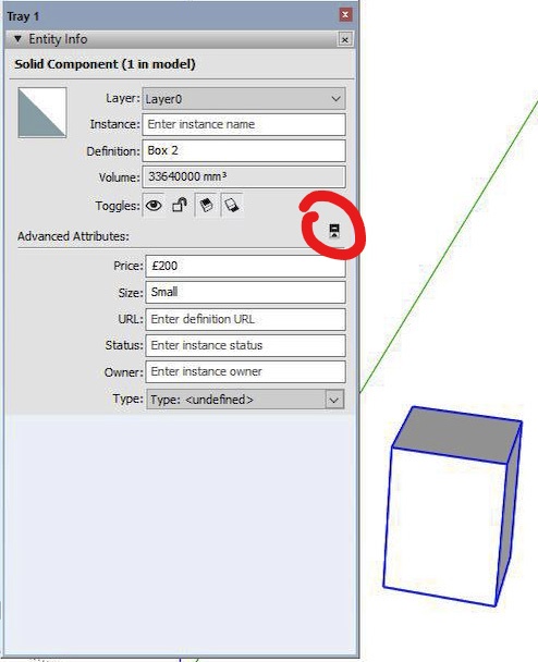
I should have added that you may need to grab the bottom edge of the panel and pull it down to expose the button. Apologies! On checking, it would seem that the entity info tray panel is the only one (panel with expander button) where the said button is not located at the top of the panel and will therefore not always be visible.
Posts
-
RE: Advanced component attributes - view
-
RE: Advanced component attributes - view
The advanced attributes can be accessed within the Entity Info panel by clicking on the button highlighted in red in the attached screenshot. I believe this is what you are looking for. The price etc. values can be changed/added after the initial component creation and will affect all instances of the component.
-
RE: Convert black + white patterns to color
I don't think this can be done 'on the fly' as you have found. However, the following should work (on PC).
From the pattern palette, paint a surface with the required pattern. Select the surface and from the right click menu select 'Texture/Edit Texture Image'. I have Gimp as my preferred image editor, other editors will probably be a different sequence. When Gimp has loaded the selected texture go to the 'Image' dropdown menu and make sure 'Mode' is set to RGB. Select the pixels to change and then select the 'Bucket Fill' tool. Set the fill colour to your desired colour and fill the selected pixels. Export the image, with a new name, to a suitable folder for further use.
Back in SU, create a new material from the saved, altered image. It will now appear in the 'In Model' materials palette. If you wish to use it in other models complete a 'Save As' and save as an SKM file, again to a suitable folder. You could add it to the shipped SU patterns but it would be lost if you had to do a re-install I believe.
-
RE: Brexit
A concise and very eloquent summary by TIG. I can only suggest an answer to Joe Wood's closing question in the original post. I have no way of knowing or assessing anyone's level of confusion around a certain subject but what I do know is that the Political elite and their camp followers in the Media continue to dismiss the electorate as being uneducated, thick and unable to understand or interpret what is being said or done. It is very difficult to predict what the political landscape will look like here, in the UK, post Brexit. I do, however, predict that on the morning following the next General Election there will be a lot of former Members of Parliament waking up and wondering as to how and why they no longer have a job to go to. Perhaps, as most of them are unemployable by any reasonable set of criteria, they can use their time to reflect on their contribution to the Nation's humiliation in the eyes of the rest of the world.
-
RE: Additional geometry.
Looking at the screenshot of the Cleanup report, in particular the number of edges that have been reduced, I would hazard a guess that what the OP is seeing is not additional geometry that SU has somehow created. Instead it is contiguous edges that have come about during the normal course of modelling. Raw geometry has been joined or overlaid with more geometry. As far as I know raw geometry is sticky and each edge remains a discrete entity and will not weld or join to form a single, longer edge. I haven't used Thom Thom's cleanup plugin but it looks like its purpose is to reduce geometry by joining contiguous edges and make for a smaller SU file size.
No idea what may be causing the other reported issues.
-
RE: Shadows below ground-level
Tried this out in SU 2018 Pro using the various shipped Styles (Default & Assorted) and all versions had a similar result to the screenshot below.
A sample model would be useful to check out further.
-
RE: Entering object dimensions--arg!
I gave up trying to figure that one out a long time ago! What I have been doing is to click and drag out a rectangle that is long and thin so that a check of the Measurements box will show which way the Axis are showing up as either x/y or y/x for that particular operation.
-
RE: Importing purchased materials into SU 2018
Your purchased materials are probably JPG, PNG image files and will not directly load or appear in SU from a folder (even with a path set in 'Preferences') A new material has to be created within your model using the JPG etc file (Tray/Materials/Create material/use texture image). The material will only be available in the model it was created in unless a 'Save as' is done. SU will save the materials as a SKM file into a folder which you can specify as juju has said.
You can also drag and drop a JPG into the model you are working on. Explode it and the material will show up in the 'In model' section of the Materials tray. Again, you will need to complete a 'Save as' to a custom folder (as juju has pointed out) in order to have the new material available to use in other models and not be lost during an upgrade.
-
RE: Tracing Walls with the Stroke Tool
I think Rose123 means the 'Lines' tool. Go to the tray panels and select Shape Style & un-check Fill which is above the Stroke option.
-
RE: Marketing Brochures the Full Job!
Clean, uncluttered with light effect that doesn't seem natural but is believable, if you get my drift! Excellent graphics, thanks for sharing.
-
RE: Component orientation
Just realised that the insertion point (Component axis) of the pump should have been set at the mid point between the two valves. Revised SKP attached.
-
Component orientation
I have been modelling a part of my central heating system and found that orientating components to pipe runs can be a bit of a slow process. Each component can be set-up to have a convenient insertion point (Component axis) but a succession of moves, rotations or 'flip along' is then needed to position the component to the pipe run. In the case of a 90 degree elbow that could be one of (sixteen?) variations.
In the first two screenshots a generic pump is shown with it's selection bounding box and move compass. It's insertion point is the centreline of the valves. If the pump is now rotated using the move compass the valves will move away from the vertical pipe centre.
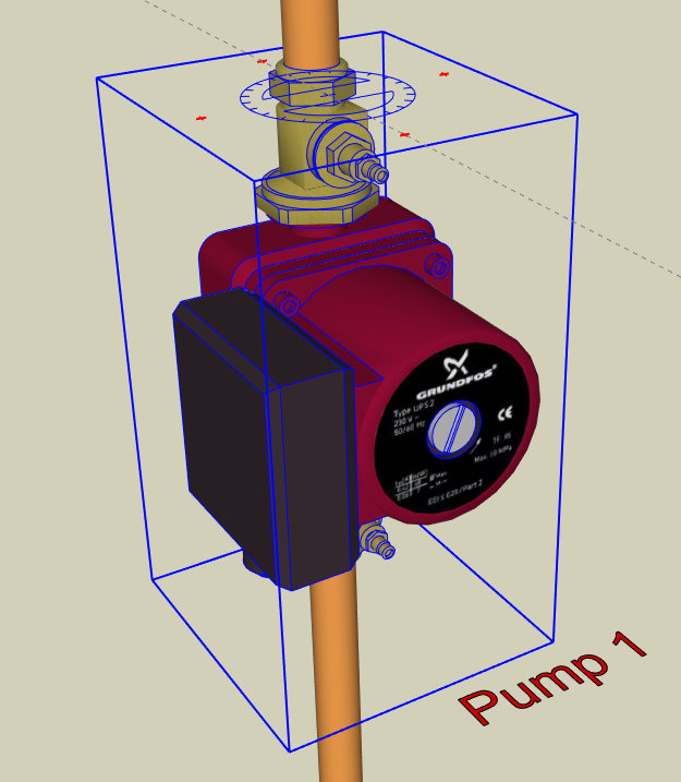
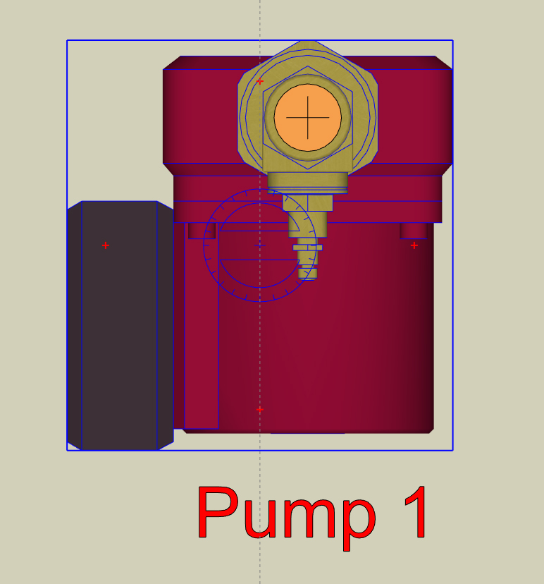
To make adjusting the pump position easier I have placed hidden planes within the component. I used squares but circles would work as well. The hidden plane should overlap all the other geometry and be centred on the point of desired rotation. The next two screenshots show the same pump with a larger bounding box and the move compass centred on the pipe centre.
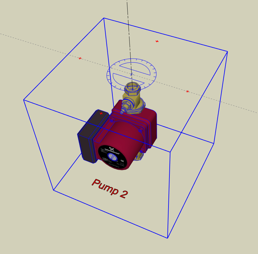
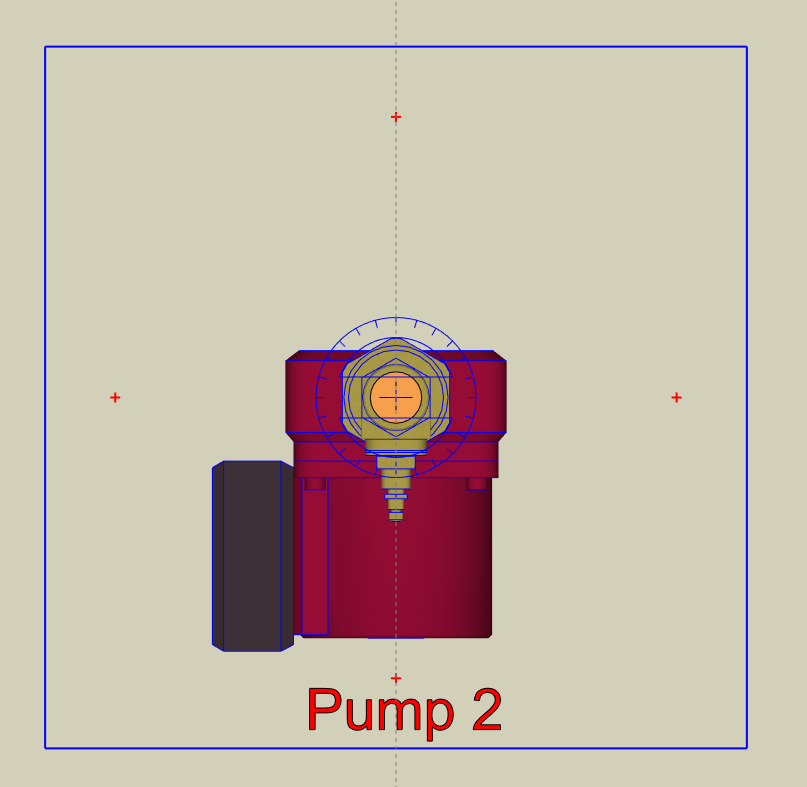
Lastly, a screenshot of the pump with the planes unhidden plus a couple of pipe fittings with the same process applied. Using this method the component can be rotated into alignment with the pipe using just the move compass. In essence, the hidden planes force the centroid of the component to be where the axis of rotation are the most useful.
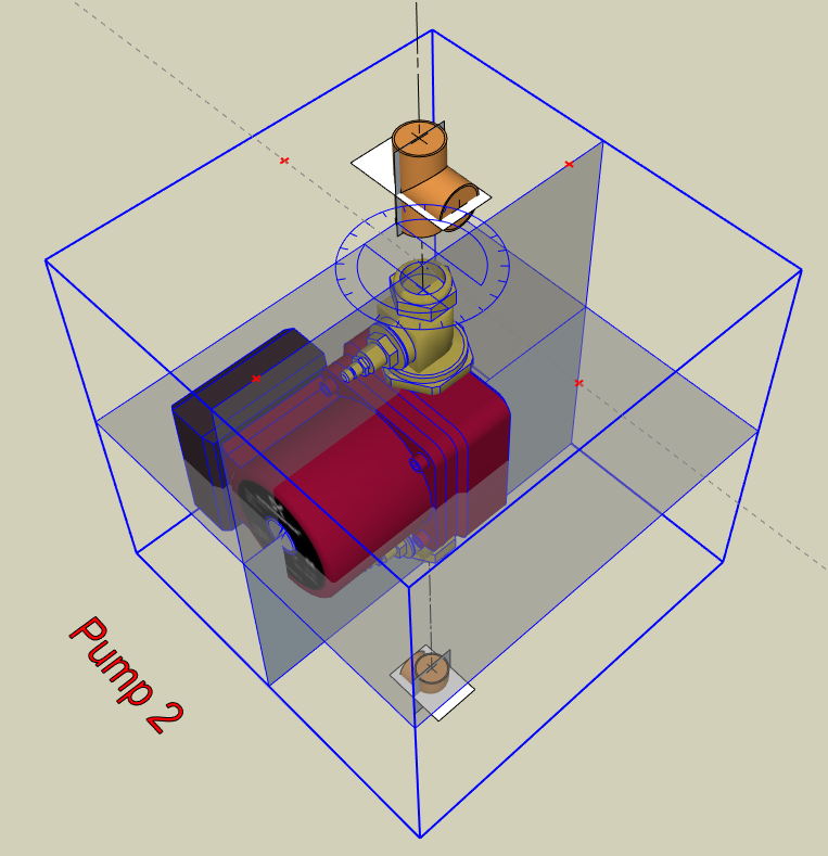
Also, I attach a SKP (version 2015) file with the pump and pipe fitting components to try out as it will probably be easier to work with than my written explanation! I hope this may be useful and, of course, apologise if the idea has already been thought of and submitted.
Regards to all.
-
RE: Cannot seem to move edge
As TIG says, welding edges will result in a curve but even welding a succession of straight lines into a longer 'straight' line will still have Entity Info report said line as a 'curve'. It seems that SU will report any welded lines as curves no matter that each original segment was in the same plane/angle/alignment.
-
RE: Cannot seem to move edge
Just wondering - was this a profile imported from another programme? CAD etc. or a manufacturer's website?
-
RE: Cannot seem to move edge
The vertical edges are drawn as curves of just one segment (Entity info). Select these, right click & hit 'Explode curve' - bottom edges can now be moved. To test, draw an arc and draw a straight line across the arc's chord. The straight line won't move. Doesn't explain how the OP drew a curve of one segment - the ARC tool doesn't allow it.
-
RE: Measure terrain area
I would add to Box's overall method in this way: Draw a rectangle large enough to cover the terrain model and move it to a position directly above the model. Apply a transparent material with the paint bucket tool to the rectangle and then make this into a group. If you now go to the top down view (make sure the Camera is in 'parallel projection' in the Camera dropdown menu) you can draw your shape on the transparent flat surface whilst looking at the terrain beneath for reference. Continue then with Box's method of projecting the shape down onto the terrain.
-
RE: Model steam engine
Thanks to all for the constructive comments. My Projects folder is littered with models that became too complex and unwieldy because I always end up putting in more than is needed. Hence the inclusion of the lamp. L i am's suggestion for further modelling is very tempting but would I end up with a de-luxe virtual Meccano set?

Attached renders (two posts) with only the engine and, I hope, a simpler presentation.
-
RE: Model steam engine
That's a fair comment Box - the 'two for one' idea didn't quite work then!