The vertical jumps now look at lot better. So far it seems pretty solid:

The vertical jumps now look at lot better. So far it seems pretty solid:

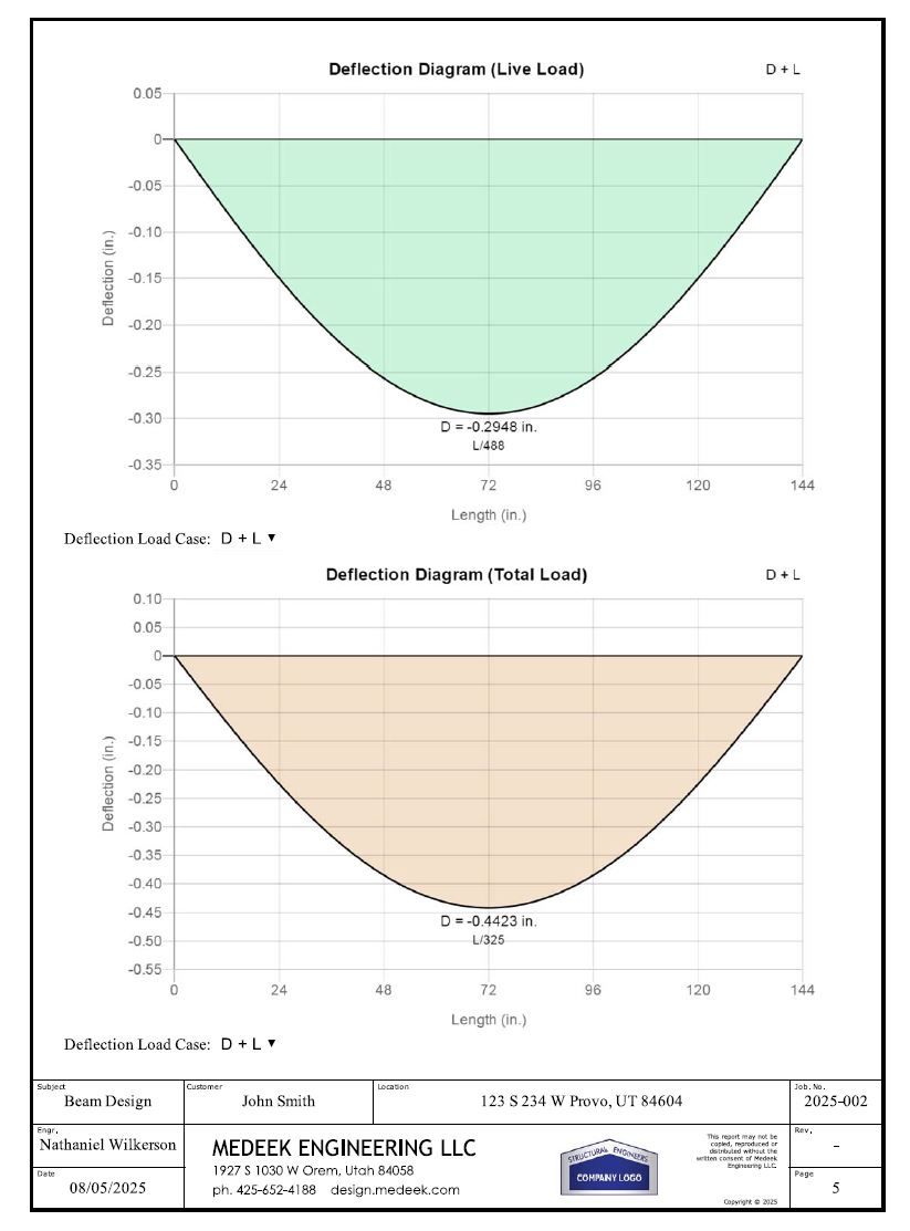
Here are the different EB (Euler-Bernoulli) and TIMO (Timoshenko) deflections for the same simple supported beam with a basic UDL (no self weight, just the external load applied) :
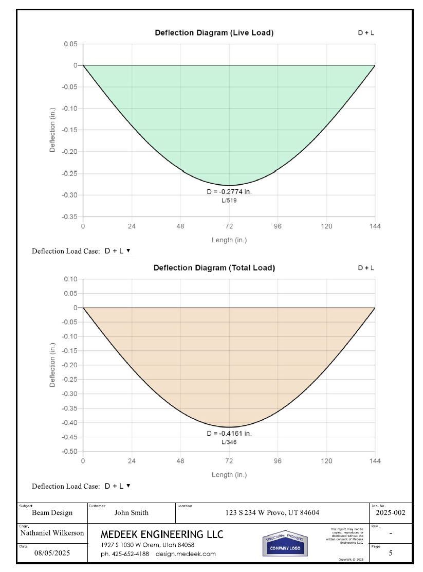
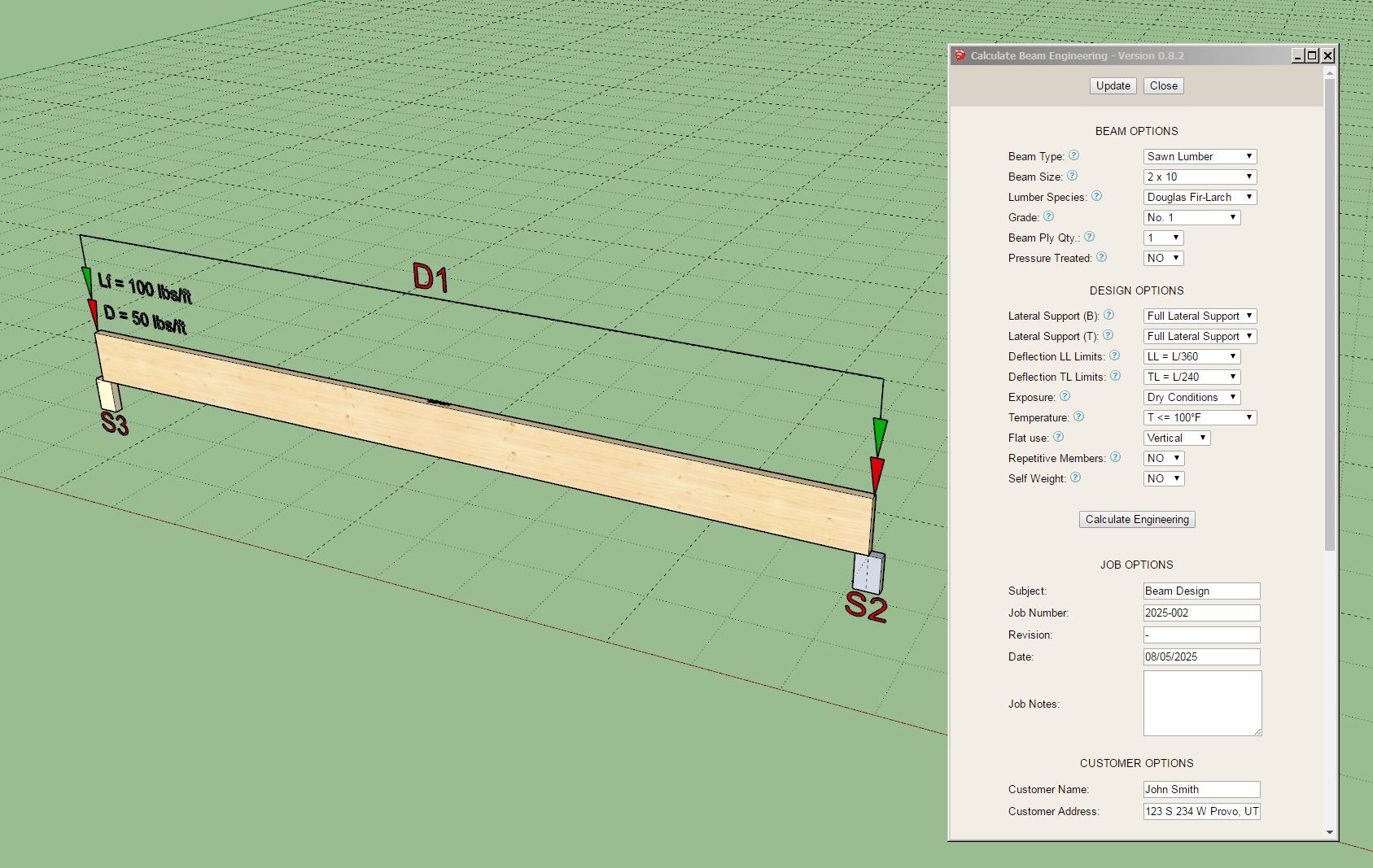


My parameters are:
2Ć10, L=144 in, E=1.7e6 psi, I=98.931 inā“, A=13.875 in², G=106250 psi, Īŗ=5/6
As you can see the Timoshenko analysis yields slightly more deflection since we are accounting for deflection from both shear and bending. According to my calculations my results are within less than 0.05% of the theoretical value so I think the algorithm is working correctly
Now I need to check a few different multi-span configurations as well as overhangs to make sure everything is indeed robust.
When I calculate the Timoshenko beam I'm wondering if I should adjust the tabulated E value since it is being adjusted for the shear already by %3 for sawn lumber per Appendix F of the NDS (Sec. F.3). So the listed value is is actually 3% larger than the (shear-free) or true value of E.
I will be running a Thanksgiving promotion beginning Oct. 30th until Dec. 1st with 30% off of the regular mdkBIM bundle price (permanent license) using the coupon code GIVETHANKS25.
This will reduce the bundle price from $280.00 USD to $196.00 USD. This promo code does not apply to any of the extensions purchased separately. As part of this promotion a permanent license for the Electrical, HVAC and Engineering plugins will also be included upon request at no additional cost. The offer ends on Dec.1st and no rain checks will issued thereafter.

Version 0.8.3 - 11.12.2025
Tutorial 1 - Beam Calculator
I'm very excited about this release, it is the first time in history (that I know of) that one can do actual engineering all within SketchUp. The API is magical, you can turn SketchUp into just about any thing you can imagine.
First look at a sample load diagram that will be generated within the report:

I was going to include the numerical values but it clutters things up too much so I think it makes more sense to just include the appropriate tables below the diagram with all of that information.
Notice how P3 is essentially on top of D1. The point loads and distributed loads can be anywhere along the beam so things may become a little cluttered even with my best attempts at trying to make the diagram as clear as possible.
If you look at the output from Weyerhaeuser's Forte app, my diagram is similar in many respects but somewhat more detailed.
One thing I have not considered yet is what if the user wants to input negative (uplift) loads. I will need to give that some more thought and figure out if that is something I should add and then determine how to best represent an uplift load.
The other thing I realized is that unlike a truss, I'm actually only dealing with a one dimensional structural entity here. Do I really need the grid? It does help show the size of the beam (the length and depth are to scale) but otherwise there is really no need for it.
Thoughts overall?
Version 1.1.0 - 12.11.2025
Version 4.1.8 - 12.13.2025


Version 1.5.6 - 12.14.2025

After the Beam calculator I need to put together the post/column calculator, then the footing calculator, then the shear wall calculator and then maybe the FTAO shearwall calculator.
I spent about an hour trying to figure out the best way to model some of these plumbing fittings for the upcoming plumbing extension. The most basic or commonly encountered of which is probably the 90 deg. elbow or quarter turn. I decided to use the default 24 segments in a circle so that the fitting doesnāt look too blocky but now I am worried about the polycount. Here is a precisely modeled elbow (1-1/2", ABS DWV, Part No. 300).

All dimensions are in agreement with the Charlotte dimensional catalog (pg. 28). My concern is that the file/component size is 112 Kb, is this too large? There will be many such fittings in a given plumbing model, then again maybe I am overthinking this.
I will probably have to model all these fittings by hand, especially if I want them to be low poly and clean. The problem I have found with bringing in models from other vendors is that they are often messy and not even dimensionally accurate to their own documentation. I end up spending more time trying to clean things up when it is sometimes easier to create a clean model from scratch.
Version 4.1.9 - 12.16.2025
Tutorial 79 - Adding Studs (5:31 min.)
Iām thinking about adding in a tool so that one can assign labels within a load center as well as configure the circuit breakers. Thoughts on this?

Version 4.2.0 - 12.22.2025

Not a customer request, just an interesting kinematic challenge that I felt like addressing at some point. I found the previous garage door opening animation largely unsatisfactory for panel doors like these. Hopefully you can indulge me with a little gold plating... now back to the real stuff.
Version 3.7.6 - 01.07.2026


Version 4.2.1 - 01.09.2026


Version 4.2.2 - 01.11.2026

I just received a very long and detailed email from one of my power users and I was thoroughly impressed with many of the suggestions and usability notes provided to me.
A long standing issue has been wall cladding as it relates to exterior trim of windows and doors. Up until now if you place your trim on the sheathing (not on cladding) then the trim interferes with the cladding. This usually isn't too big of a problem (visually) provided your cladding is not thicker than your trim. However, in the real world you generally install your trim first and then butt your cladding up to it, so there is no interference. When your cladding is thicker than your trim or you are using one of the 3D cladding options (ie. board and batten) this does become a bit of an issue and for me personally has been an annoying lack of realism now for a few years.
To fix this I needed to enable an option where one can toggle the trimming of the cladding by the exterior trim and then add some logic and geometry into the current algorithms so that the end result is as follows:

I won't bore you with the details of the rather complicated logic under the hood that accomplishes this but suffice it to say it is not trivial. It will take about 4-5 days to complete this update.
The window algorithms are now updated but I will need to update the door and garage door methods as well now.
In the global settings one will be able to independently toggle this on and off for windows, doors and garage doors. I will also probably put out another tutorial video on this feature specifically so that everyone is clear on how it works.
Version 4.2.8 - 01.27.2026


Update per customer request.
You can now add round steel in-wall columns into your Medeek walls. These aren't actually lally columns since that specific product is typically installed with an adjustable screw assembly. However for most design purposes I think showing the round column like the image above will suffice.