In commemoration of the 250th anniversary of the Unites States of America I am running a month long promotion for the mdkBIM suite. This promotion applies to new customers as well as existing customers, and with the coupon code USA250 gives a 20% discount on the purchase of the mdkBIM suite.
This promotion runs from July 1, 2026 to July 31, 2026. All purchases of the mdkBIM suite prior and after this time frame will be at the regular price. This will reduce the regular bundle price from $330.00 USD to $264.00 USD. This promo code does not apply to any of the extensions purchased separately, subscription licenses or to permanent license renewals.
Now the important part, and why I think this promo is also a decent value for existing customers who might be thinking about renewing their licenses. As part of this promotion a permanent license for the Electrical, HVAC and Engineering plugins will also be included (upon request) at no additional cost. This offer ends on July 31st and no rain checks will be given thereafter.
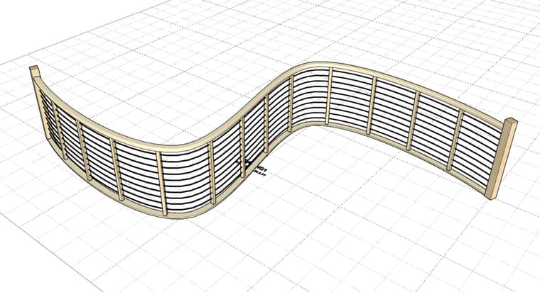
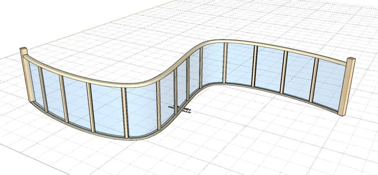
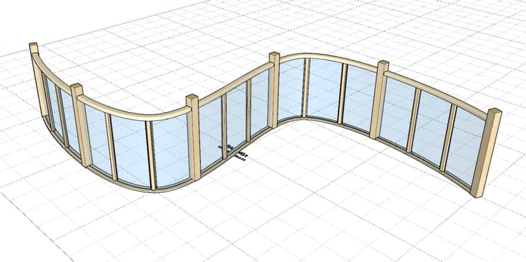
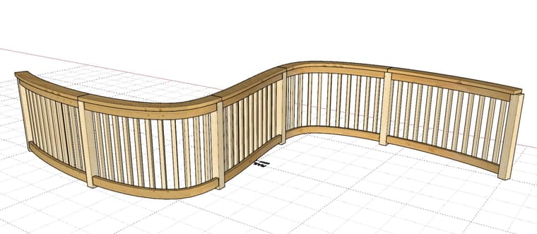
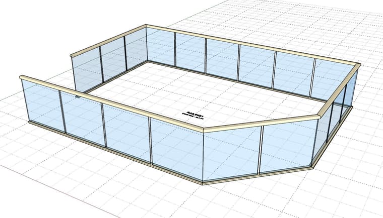
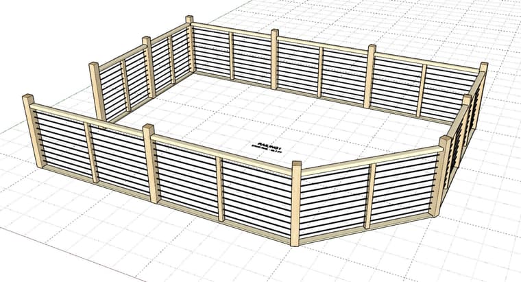
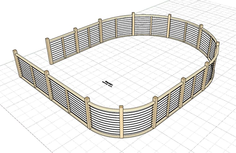
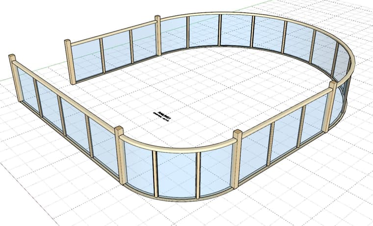
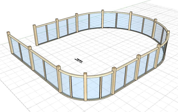
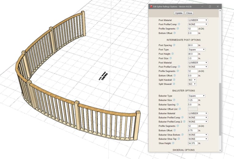
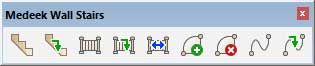
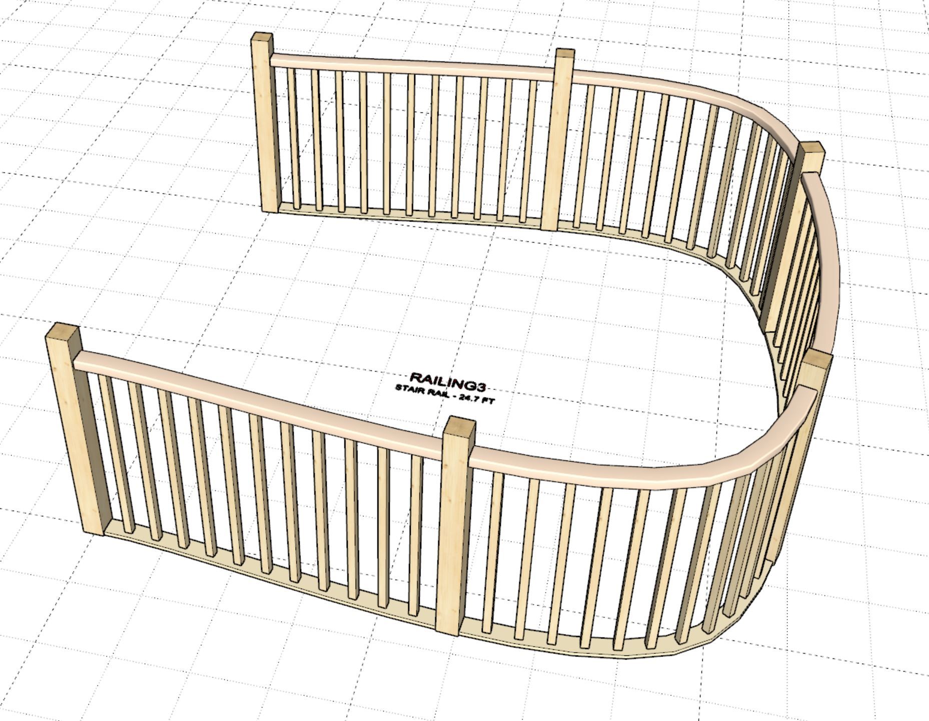
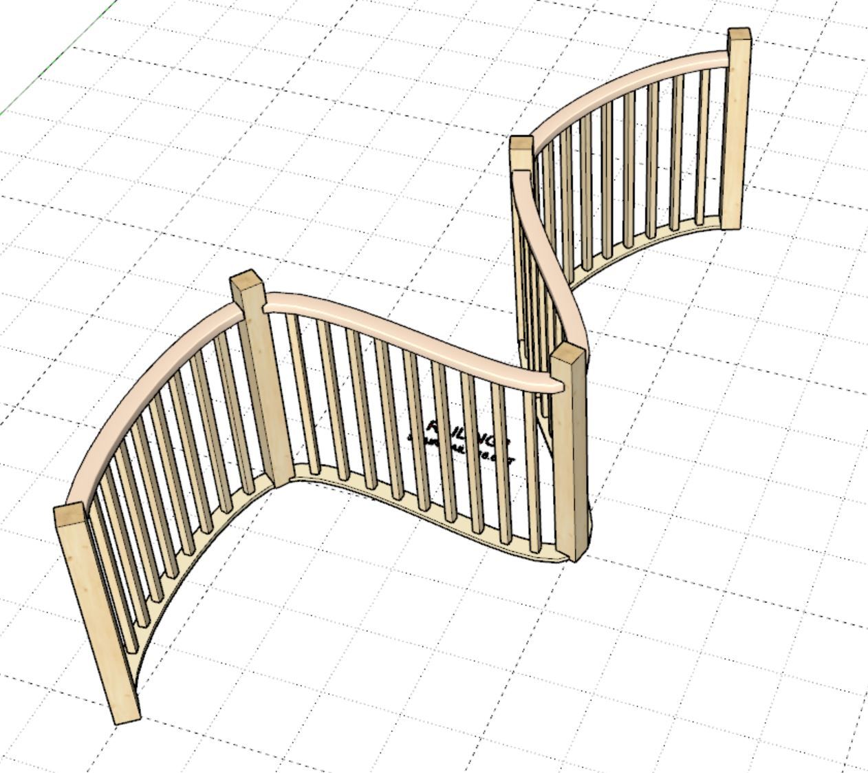
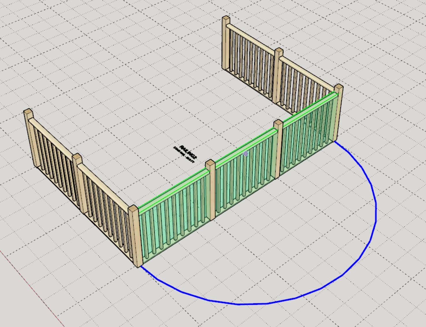
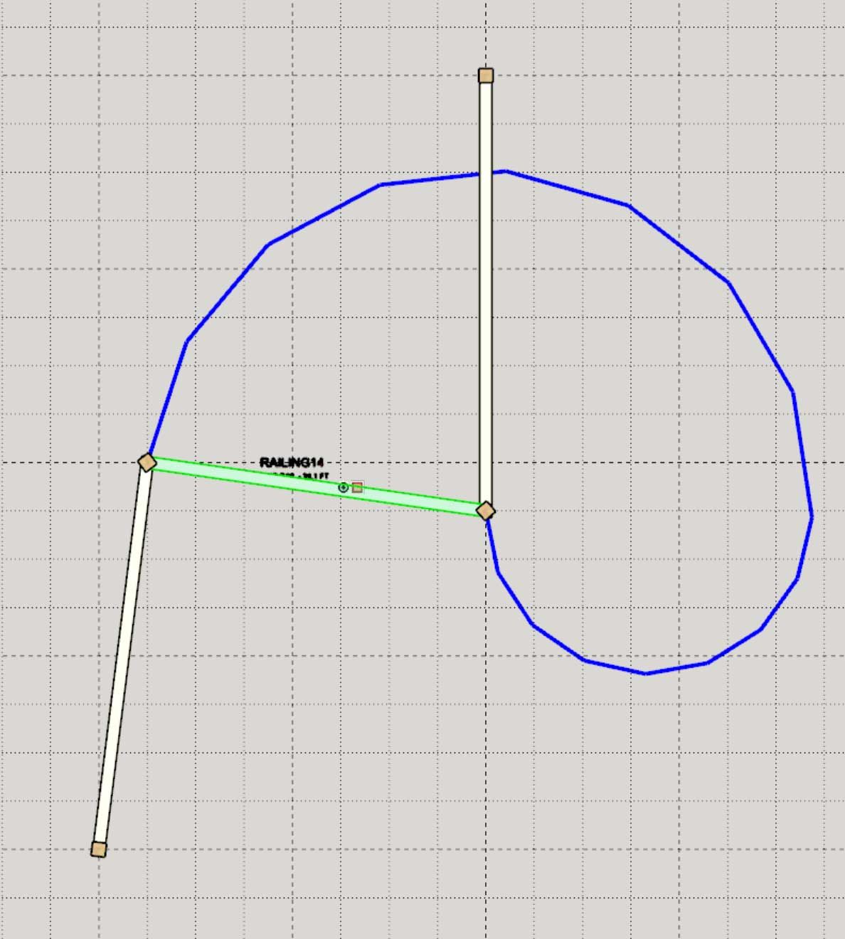
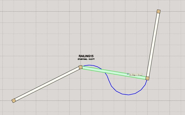
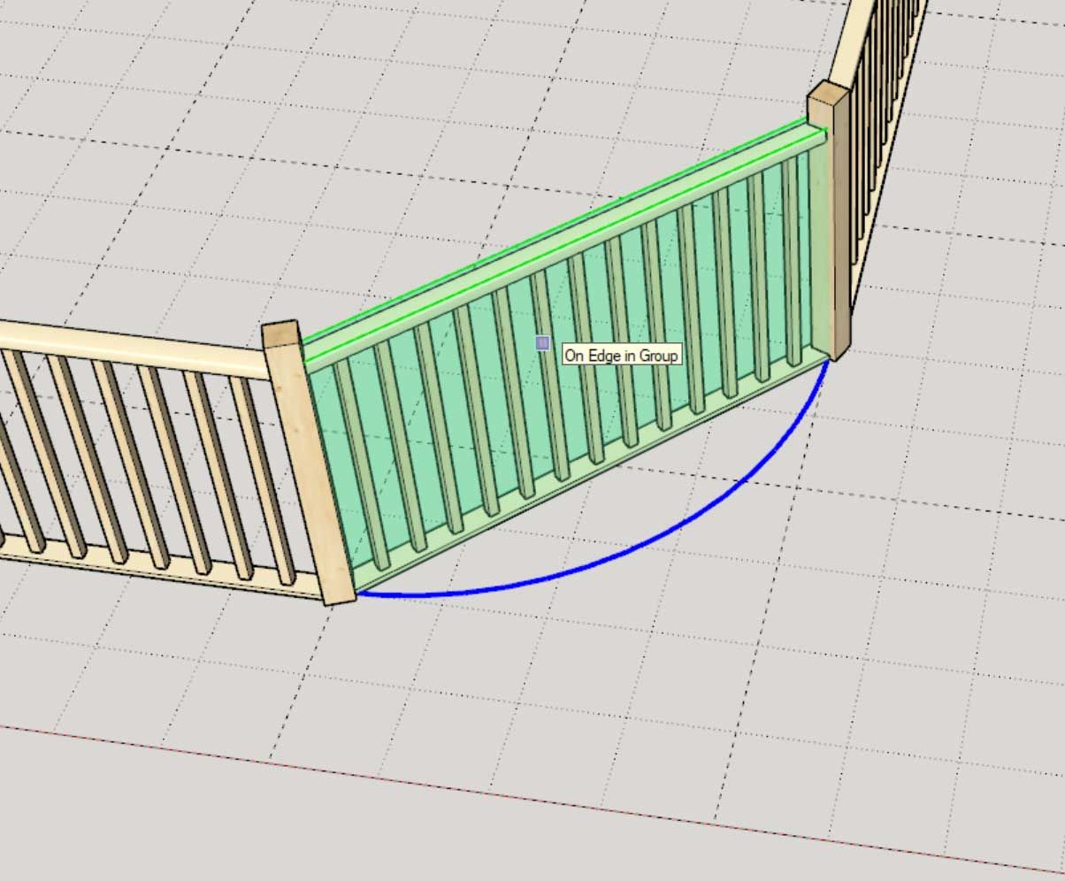
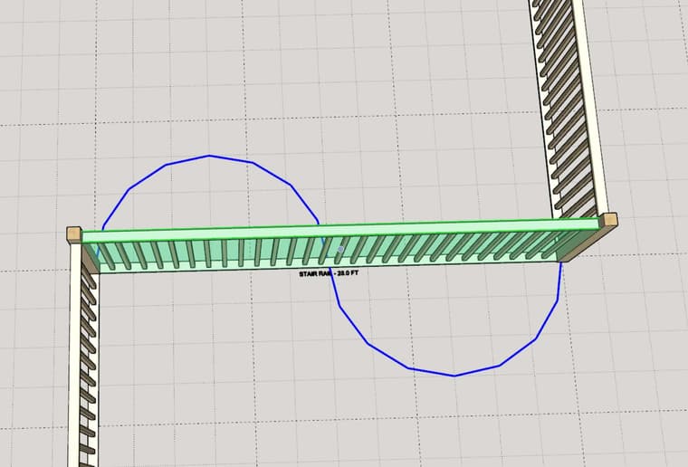
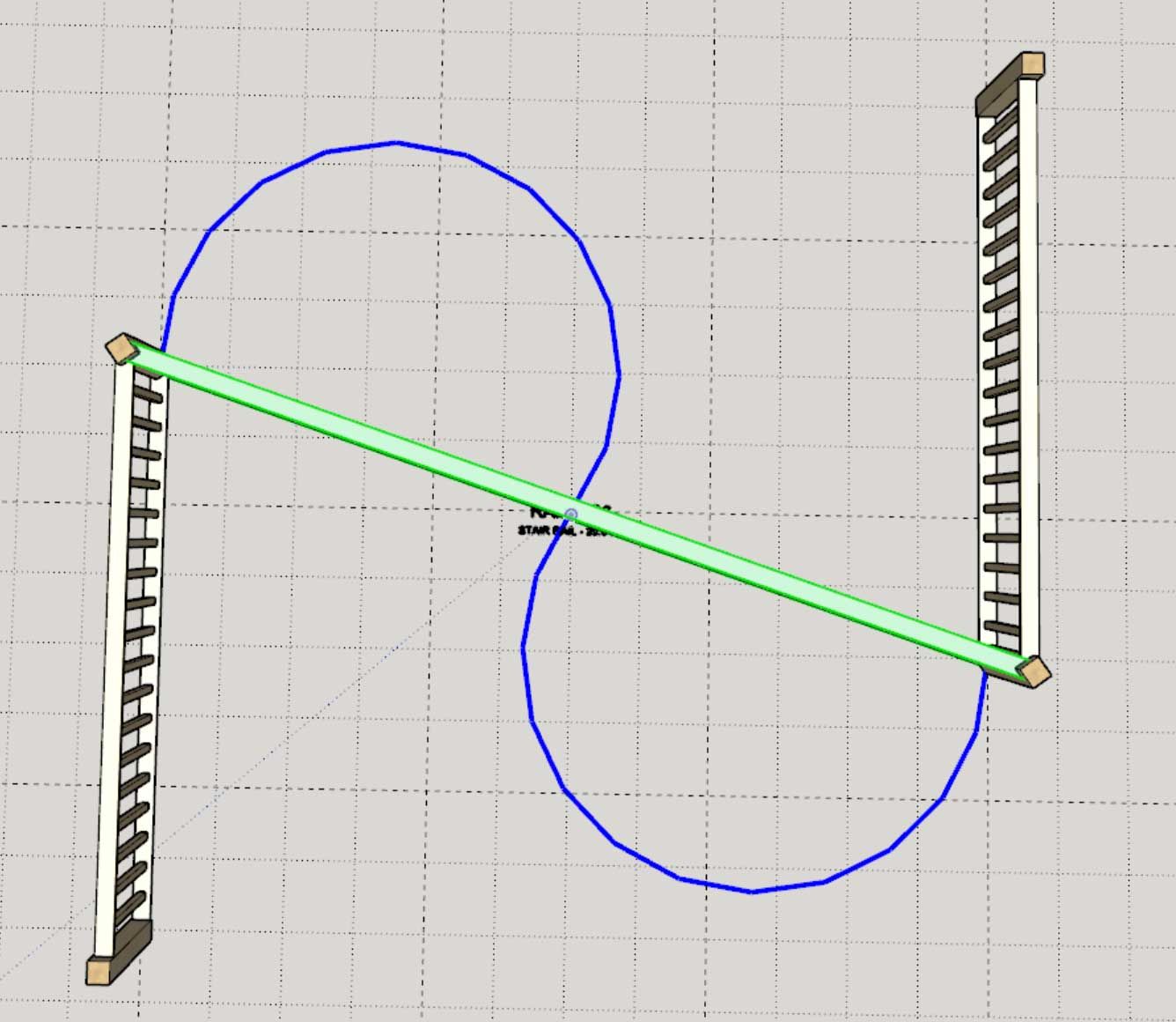
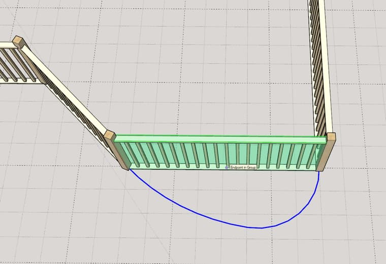
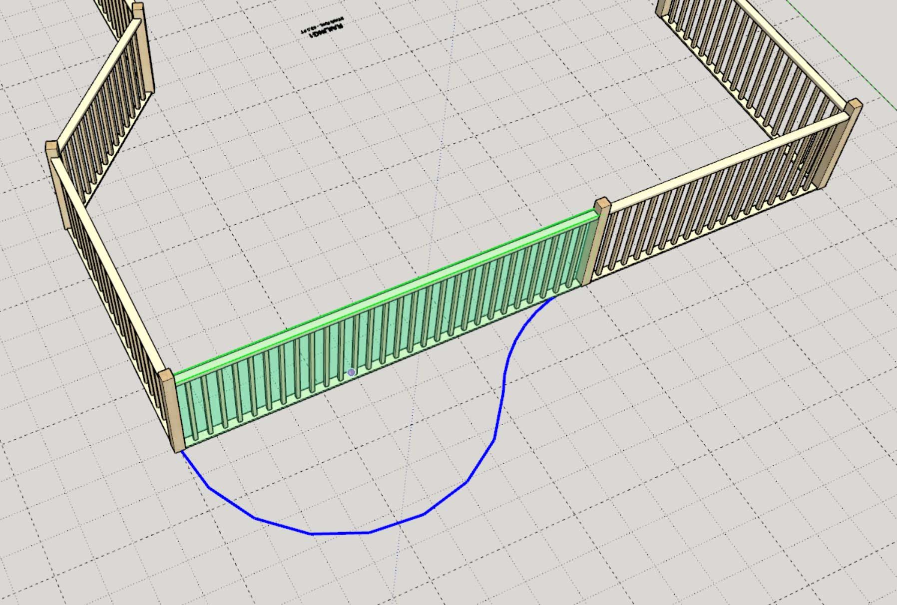
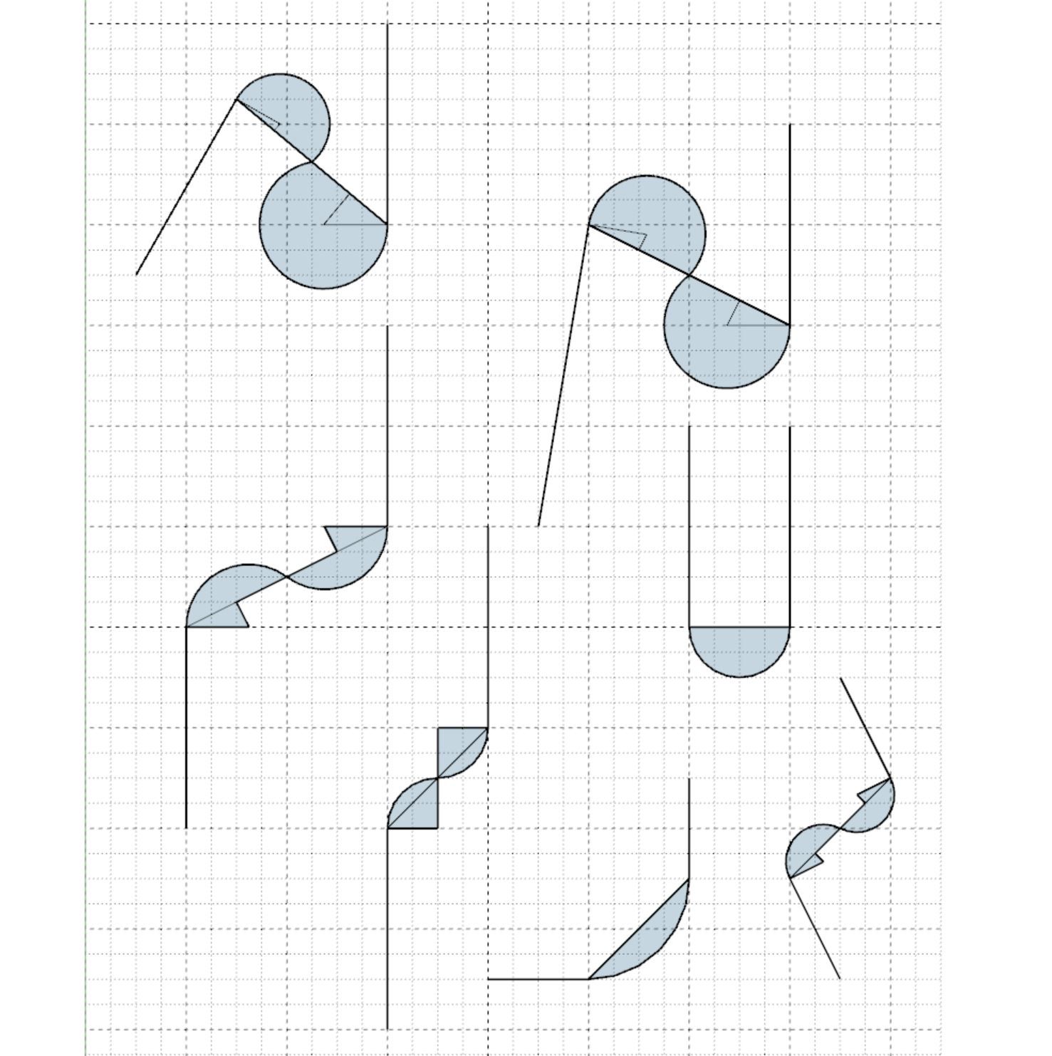
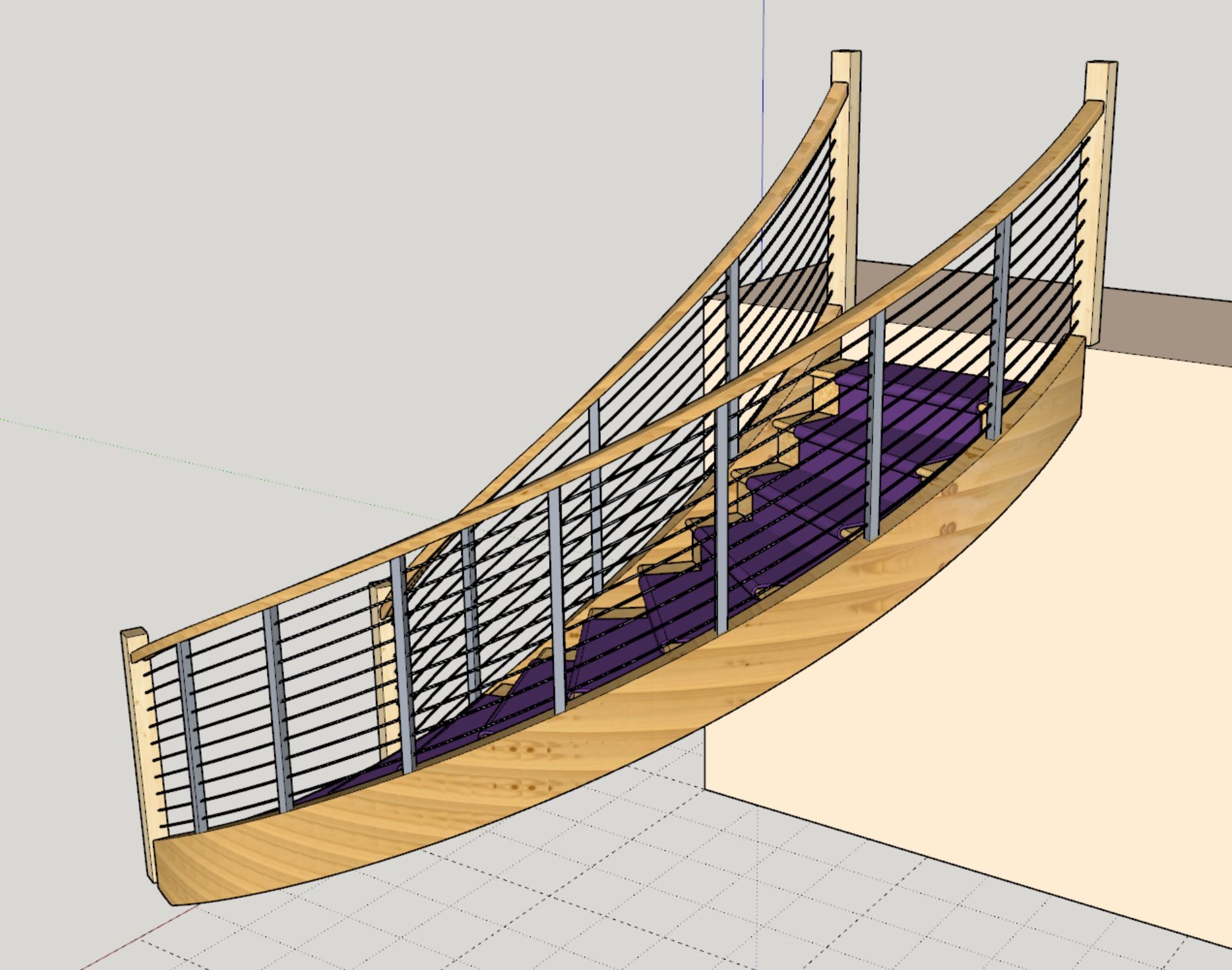
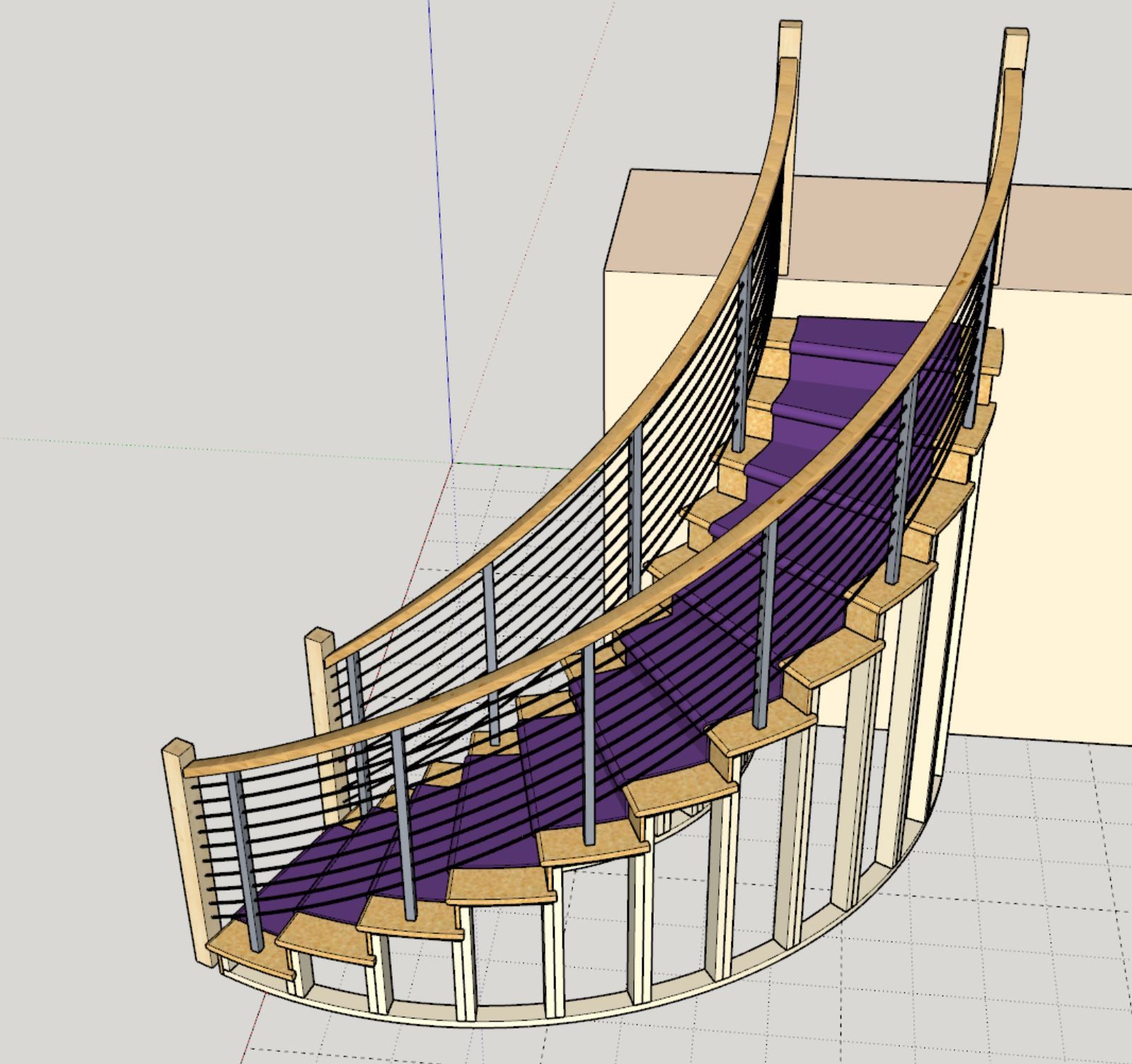
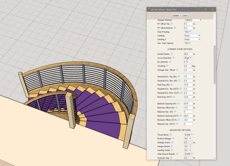
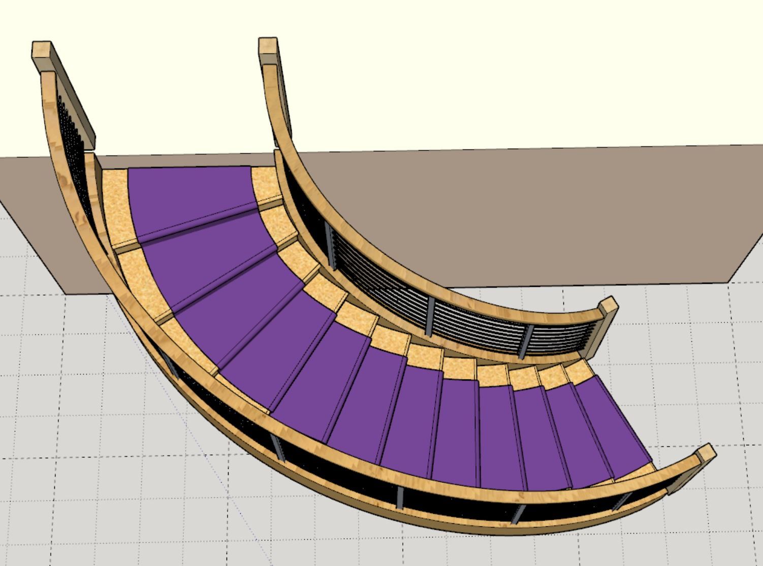
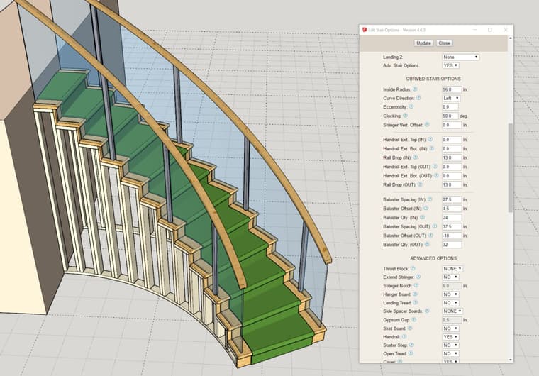
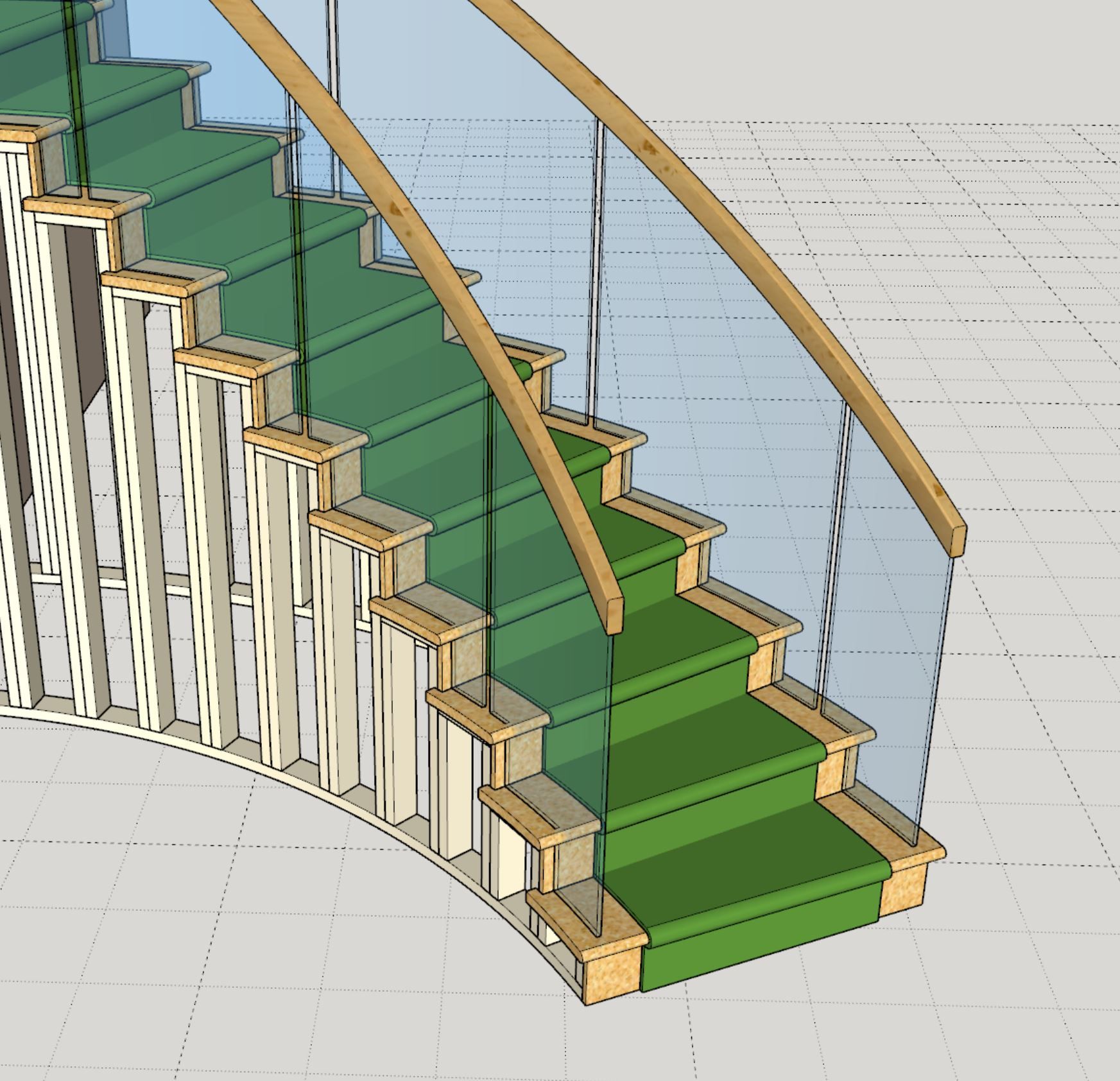
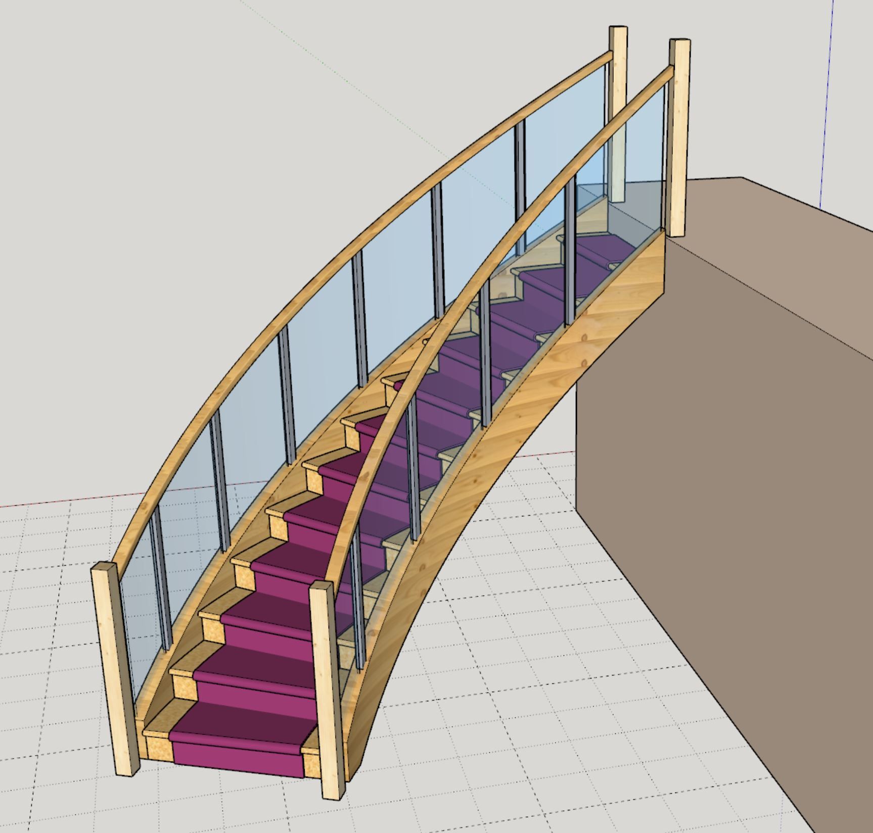
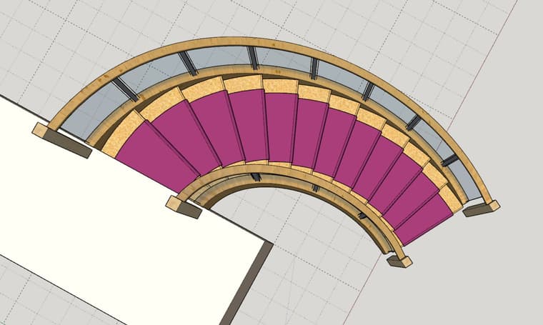
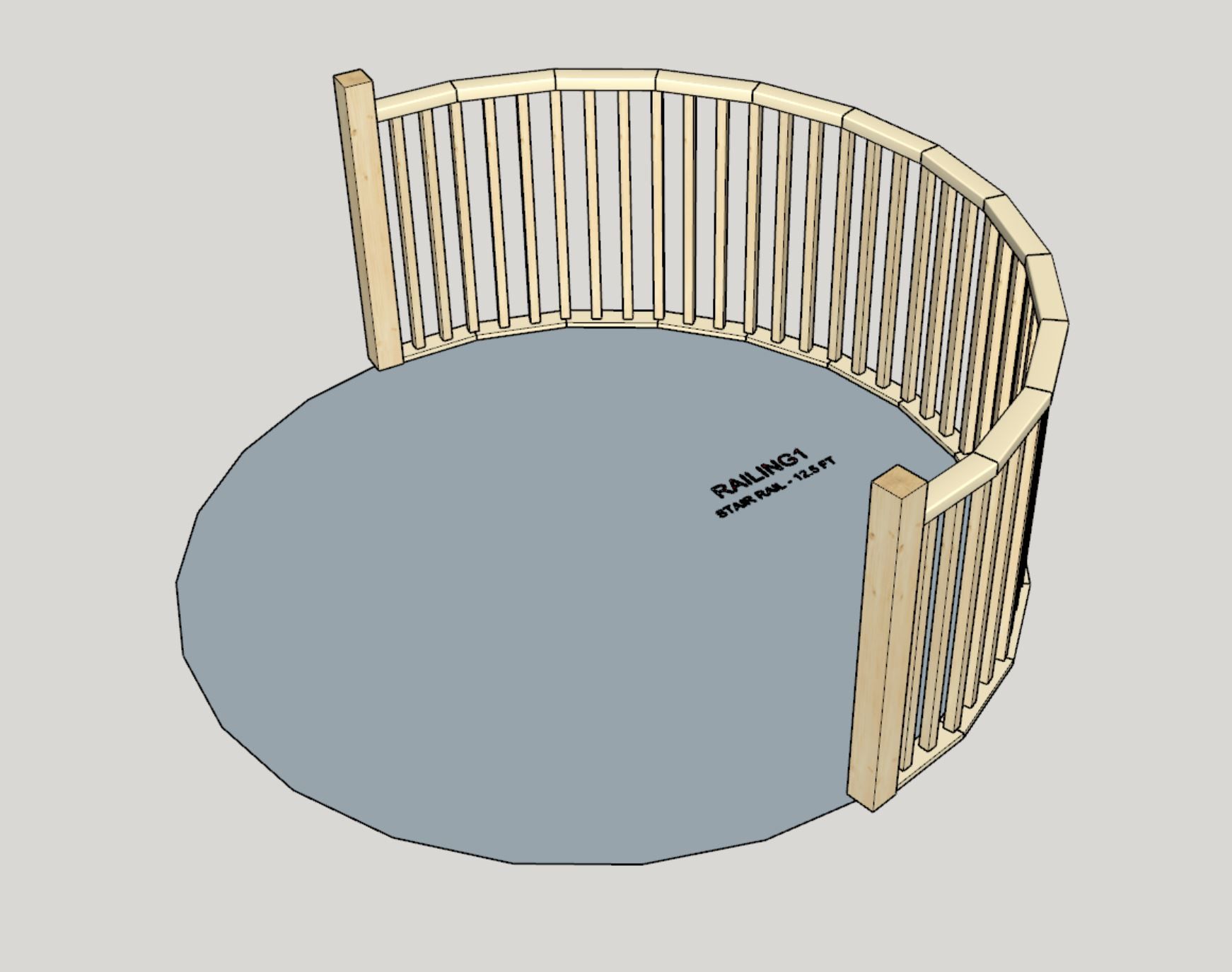
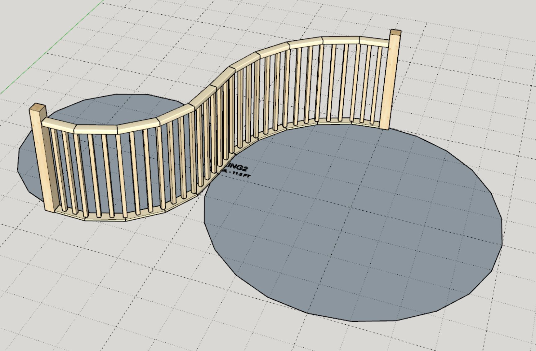
During the last few weeks I have been focused primarily on the stair and railing modules within the Wall plugin. I am happy to announce that significant progress has been made on that front and I strongly encourage everyone to check out the new updates and watch some of the latest tutorial videos which demonstrate these new capabilities. A huge shout out to Patrick O'Brien and Larry Belk for taking the time to encourage me and push me even further in this regard. Without their feedback and insistence I might not have progressed these two modules as far as I did.
I would also like to take the time to thank everyone for their support of the plugins these past 10 years, it has been quite a journey and I am very much looking forward to another 10 years of productive improvements and many feature additions, and who knows, maybe a few new plugins.
Nathaniel P. Wilkerson
nathan@medeek.com