A new project... getting a bit faster. Still wishing for some more intuitive tools, and still wishing LayOut wasn't so damned slow...
A new project... getting a bit faster. Still wishing for some more intuitive tools, and still wishing LayOut wasn't so damned slow...
@dave r said:
Back in the early 80s when I was in Fine Art school at the University of Wisconsin-Madison, I was shown a series of hand painted cards that showed the color illusions very well. The name of the artist who painted them escapes me but it was a powerful thing to see.
Josef Albers.... classic art school and fine art training. If you have access to the originals or a hand printed copy - they are incredible.

nice. just downloaded this and need to start playing with it.
i like seeing people and 'life' in schematics, renders, etc.
architecture without people... seems a bit odd to me.
i mean, buildings are typically for people...
but your mileage may vary. to each his / her own.
You might want to create some dummy groups / components that can be turned on and off. Copy the items you want to highlight, move these to the side, create a group or component. Change the materials, properties, etc. Delete what you do not want, then move them back into place. Use the Outliner or layers to control visibility. These could be a specific color (transparent red) or some other style that highlight how the load moves down into the model.
And you could also then bring these into Layout, set up a view with your model, then set up another scene with just the dummy components on - but at the same scale, (and other identical settings). Explode this view - Layout will turn it into 2D graphics. You can then position these over the original view to highlight how you want your drawing to appear.
And look for TIGs section cut face tool - it automates the process of filling in section cuts - so you can edit these a bit quicker - perhaps adding color to how the load moves through the structure.
@redinhawaii said:
I know how to cut in a real roof, I just feel it bit too much like work to have to individually push pull each rafter, and the sheathing.
It would seem there is a need for a "slice or cut tool" or ruby, i.e. "anything touching this plane is separated from it's geometry".....
how do you cut a hole in a wall as a simplified example... maybe I should try that...but sep. groups here...
thanks
like to see how your roof comes out, too.
aloha
red
couple of ways to get there:
if your rafters are all components - then simply drawing a construction line down from the face of the wall tracing it onto a rafter and clipping off the excess will alter all similar rafters. you'll need to go and adjust any thing that is 'unique'.
if they are all different (or not components) - copy the components you want to cut off to the side, leaving the originals in place. create a 'dummy' mass of the second floor - just a big block the same size. copy it over to the same location as the components above. open the various components that you need sliced. triple click once opened to select all geometry. right click. intersect with model. this will draw lines on your component(s) where they intersect that dummy block. delete what is unnecessary. again - any component that is identical will automatically alter... and you'll have to repeat for all components that are unique.
i'm a fan of building my model as i would with hammer and saw out in the field - so i'd go through the trouble of building my roof with repeatable rafter components to minimize work down the road, then cutting them to a ledger or ridge as needed to rest against the mass of the second floor. if you go through the trouble of modeling it correctly - you'll be able to use those details later on for construction documents.
Red- you can cut through the roof - you'll just need to edit that component and get in there and draw it all out... ledgers, plates, rafters, etc. interfacing the walls and floor systems. Build your model like you'd build it in the real world.
I'm doing that now on a project that has 3-4 roof lines all colliding at different levels with floors, overhangs, porches, etc.
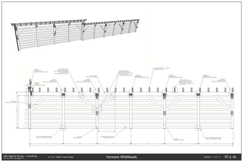
Been playing with the 'bend' portion of this plugin.
Took the straight version and made it into the bent version.
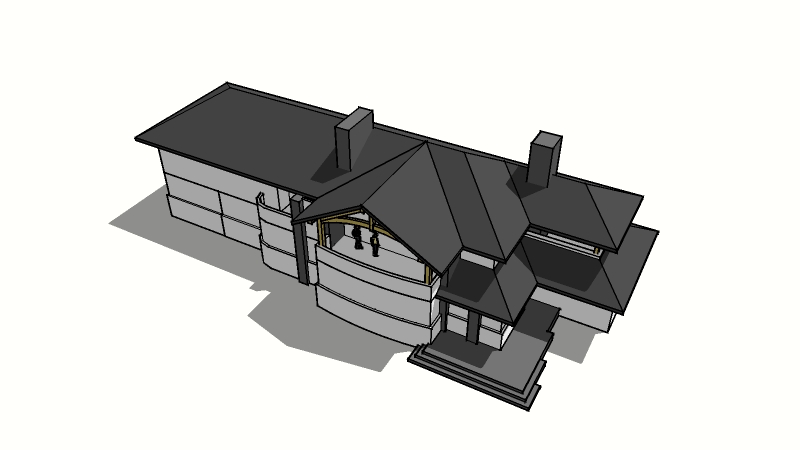
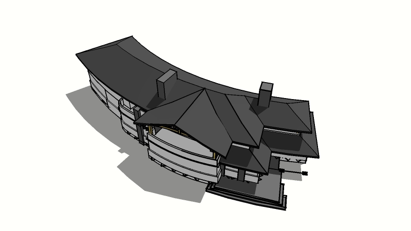
I included the original 2d floorplans embedded in the model.
Crashed the machine a few times - but I cleaned it up, simplified the original a bit... and it worked.
I'd love to understand the math on getting the bend to meet a particular arc or radius. I drew a circle of the correct diameter and then eyeballed the model to get it close... which is good enough to see if clients are interested in the massing / concept - and I was even able re-link to LayOut so my views were pretty close and required minimal tweaking...
To see a section slice in a model, just nudge it away from your section plane by .01 or .1 inches (depending on scale / units / etc.).
Works great...
TIG's tool sounds great - but I use the built in tool to create a group, nudge it into the part of the model that is showing. I'll often slide it over 1000" or some handy number, make it into a component, and then edit, fill in the solids with various colors, textures, etc.
Then detail it in LayOut.
just downloaded. this should help with my longhand way of doing this!
I've found it easiest to create multiple styles and control them in the various scenes, even turning them on and off in a window in LayOut looking at my embedded model.
Styles can have sections on / off and the planes active or hidden.
When you update your scenes it may ask you to 'save a new style'. I do this, then name is something that defines what it is / how it works. Once these are set - you can apply them to ANY window in LayOut - regardless of what scene / setting you originally set the model up in... I have 2 color styles with sections on / off and 2 BW hidden line styles with sections on / off. I can quickly (relative here in LayOut!) change the entire drawing from color to BW line art...
@watkins said:
You don't say, so I assume you used Layout to make the presentation drawings. Is that the case?
are you talking to me?
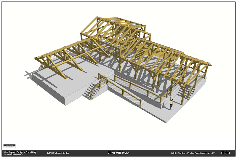
yes, i did use layout with embedded model(s) to create the tf and building model...
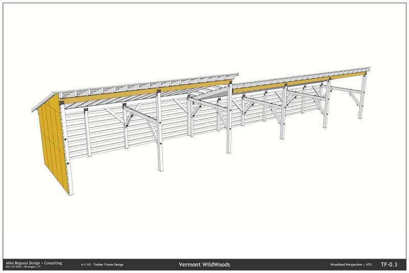
Presentation drawings for upcoming zoning meeting. I'm a timber frame designer - but do plenty of schematic work with my clients, as well as presenting how my work coordinates with others. This particular project I worked the schematic design from scratch, and will see this turned over to a local firm for CD's permits, etc.
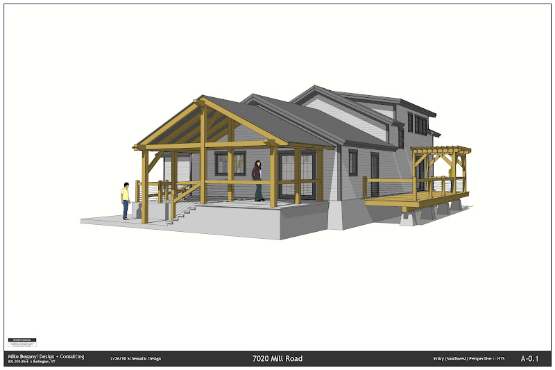
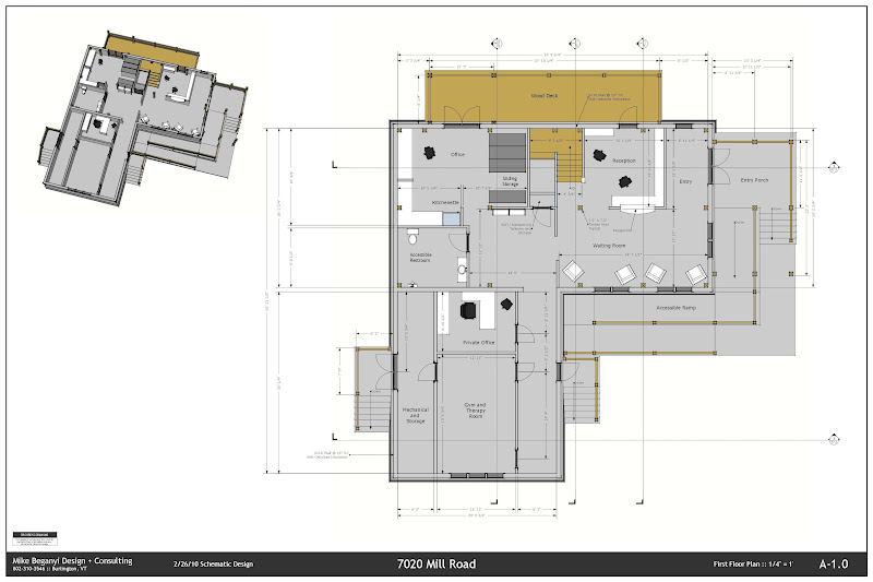
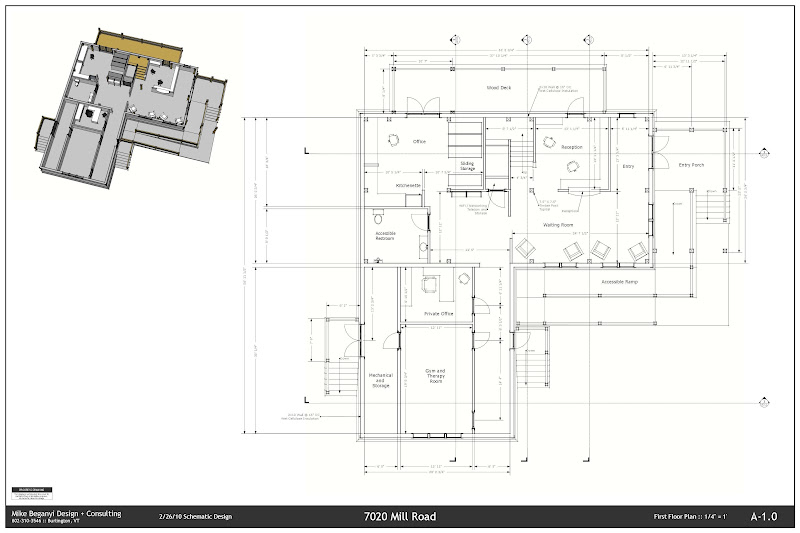
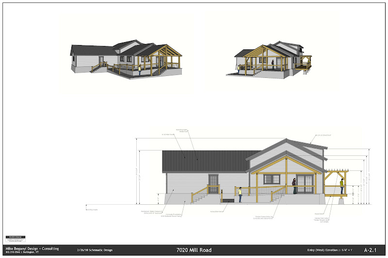
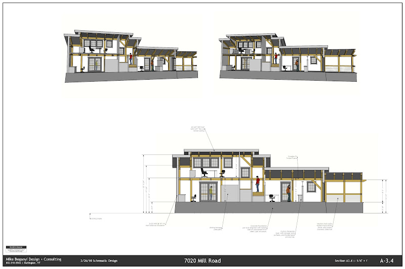
Final set submitted is about 16 sheets. Will also add a few construction detail shots of how the frame interacts with other components. I have the color set, as well as a separate set with a B/W sketch line drawing style - slightly softer than an ACAD drawing, but still crisp for a non color print.
It took a few test plots to see what font sizes I'd like and how my styles would translate to paper. I'm partial to the color versions - but if I were to take this further I'd probably do a mix of color w/without shading and line work drawings.
I've been using SketchUp to detail out various timber components and notice a huge lag in performance once I start placing dimensions. I've set the dimensions to be a particular height in the model, based on view and detail size.
Is there an optimal font or procedure for streamlining this?
Should I not be setting the dims to a particular measurement?
I'm expecting a new machine any day... but I can go from working in a relatively smooth model to grinding to pan and zoom - even after just a few dimensions. And forget about working in x-ray mode.
-Mike
@sir said:
you dont have you use bootcamp, you can use a virtual machine instead, so it runs from within the mac interface...
but thats off topic.
i havet upgraded to v7 yet as i detest the fact that they'de made it backwards incompatable
i have v6 and v7. didn't realize they weren't backwards incompatible... until i send files to folks with only v6. but i need the options to play with the dyn components and i'm enjoying (somewhat) the improvements in layout.
i'll try running it via vmware fusion - is that what you are doing?
i'll still need to boot into xp for autocad when i need to do some heavy lifting on the 3d side. until i test my worst case i won't know if an emulator will be 'good enough' for me.
that said - google finally responded and set me up with their 'sales' number for when i need to contact them about handing over $50 to transfer my license from PC to Mac.
Thanks BertB!
I'll be doing something similar... SketchUp for modeling / presentation. I'll be running AutoCAD Architecture 2009 in BootCamp for intense structural work (3rd party overlay) or VM for easier work, review, take offs, etc.
I don't do much 'rendering' aside from sketchy images that pull out as JPGs. Plenty of slideshows and walkthroughs.
-Mike
Anyone using one?
I'm thinking of picking up a 15" in February.
Switching from a Dell Inspiron.
Going to run AutoCAD 2009 and some 3rd party overlays in Bootcamp, but was hoping to run SketchUp on the Mac side. Haven't found much about the NVIDIA 9600M GT online.
I also have the chance to pick up a Lenovo W500 at a great price - but also wonder about the card in that machine - a Mobility FireGL V5700... lots of driver and BIOS issues.
Not an issue yet - but will be in about 3 weeks when I migrate to a MacBook Pro from my PC.
I've emailed and formed on the Google 'sales' site several times now with 0 success.
I want to have everything ready to transfer - so I need to swap my license from PC to Mac (or run in XP in Bootcamp... which I'm trying to avoid).
Still no luck, even after rebuilding everything. When I swap for the joinery component I can't get an updated overall length.
Will post a model later.
Thanks for the input.
I worked on an updated model - I added a Z length to the parent component and noticed I had some strange scaling behavior in the original joinery. Fixing these makes the results more predictable.
I'm still not getting an overall length when I add the joinery...
And I'm getting some weird behavior dealing with other dimensions now...
But I think I see a way to address this. I will rebuild them from scratch and see if it improves.
Broken down by Entity Name in Col3, check the LenZ# in Col12 - look for the following to see where I'm confused:
Entity Name T1 - LenZ should be 48, it is reporting 17.015
Entity Name T1A - LenZ shoudl be 96, it is reporting 34.030
*note, the subcomponent in the row below the ones listed above is showing correctly
Adding the joinery, I thought the LenZ would be the accumulation of all the components in the parent. This is not the case, the LenZ of the beam with joinery on the ends is reporting smaller than in the model:
Entity Name T2B - LenZ should be 120, it is reporting 34.030
Nowhere in my report do I see the same values as the dimensions (converted to inches) as I have in the model, with the exception of the subcomponent 'beam'
-Mike