[Plugin][$] Curviloft 2.0a - 31 Mar 24 (Loft & Skinning)
-
The information on Curviloft is maintained on the Plugin Home Page of Curviloft. This is also where you can download the RBZ file.

-
LibFredo6: v14.3b or above
-
Sketchucation ExtensionStore: v4.4.0 or above (for licensing)
-
Sketchup version: SU2017 and above
-
Platform: Windows and Mac OSX
-
Usage: Licensed under Sketchucation SCFLicense
-
Free Trial period (full features): 30 days from first usage
-
Perpetual license (3 seats): $15
-
Part of Fredo6Bundle2022 license (8 plugins): $50
If you land on this page and are unfamiliar with how to install Sketchup Extensions such as LibFredo6 or how to register on Sketchucation, please watch this video or refer to the Plugin page of LibFredo6.
To purchase the license of Curviloft or the Bundle of 8 plugins, go to this page and sign in.

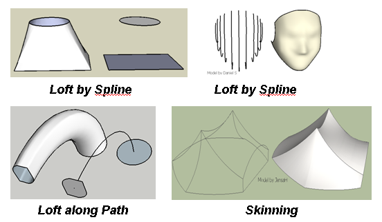
Curviloft is a script dedicated to Loft and Skinning, that is, generation of surfaces from contours.
- Loft by Spline joins separate contours, open or closed, by smooth splines
- Loft along Path joins contours, along a given rail curve.
- Skinning create surfaces bounded by 4 or 3 contiguous contours
Because there are many solutions to calculate Loft and Skinning geometries, the script offers various options to adjust parameters depending on the configuration of contours.
-
-
Hi Fredo,
Great to hear it's getting close to release! The video is amazing

Will post back with examples for testing
Thanks for sharing
Rich
-
Fredo!!!
you are a genius!!!I don´t know if something like this one will work...
but here I attach a panton chair.I have to see this video again and again

Daniel S
-
@daniel s said:
I don´t know if something like this one will work...
but here I attach a panton chair.Daniel S
Daniel,
I had to put some splitter (i.e. line) to get contours with 4 parts.
Here is the file and a short video.
Fredo
-
Looks like it is the most powerful plugin ever made.
Daniel S
-
I feel like a kid at christmas time who knows what he's getting but can't open his present yet!!!!
You never seem to amaze, Fredo!
-
Looks fantastic, really looking forward to seeing the finished product in operation.
-
WOW! Way to go!
Any chance, once a skin is made, that could be some axial controls that could be dragged to do stretching such that the skin would react like what is done in Soapskin and Bubbles where the forming edges are anchored and the skin stretches relative to the forming edges? Perhaps have a tightness parameter to control how close the skin conforms to a path or to the defining edges? Could the path be altered interactively to reshape the skin?
Tapering. Really would like to create Reduced Elbows for Piping or Ducting systems. Draw a "welded" curve for a path, place circle or "donut" tangential at each end of the path with specific radii/diameter and then form the skin of pipe (inner diameter as well as outer diameter too?). Have a means to minimize the amount a faces formed. Transitions of the ribbing of pipe would be linear versus what looks like an averaging method used in your video for "freeform" skins. It would be fantastic if the end diameters were parametric so user could change their values.
John
-
Holy crap!!! Is that speed realtime? Looks amazing! Do the number of segments in the rails matter? Could this possibly be used to replace the standard from contours in the sandbox tools to create graded terrains?
-
WOW! i love how you ruby greats are dragging SU kicking and screaming into the realm of a "real" 3d modeling program!

screw you google. if you won't give us proper tools someone will.
thanks Fredo, and everyone; TIG, ThomThom, Chris, Jim, Dedier, Whaat... just to name a few. you guys ARE the real SU team. all we really need from google is poly support. you guys cover the rest.

-
BRAVO FREDO
-
Really big thanks for investing so much time to give us so niceeeee plugins !! I'll try to post a file to test it on terrain modelling, which is my main occupation in SU.
-
Looking very nice. Can one edit the control splines afterwards?
1:24 - Float Pal window: is that done using
view.draw*method? -
The Fredo return!

What a teaser!
What about make a thickness to a surface?
-
@unknownuser said:
The Fredo return!
What a teaser!What about make a thickness to a surface?
I guess this is a job for JPP. Curviloft only generates the thin surface.
Fredo
-
@thomthom said:
Looking very nice. Can one edit the control splines afterwards?
1:24 - Float Pal window: is that done using
view.draw*method?Tom,
Yes the button palettes are all based on
view.drawmethods. And for Curviloft, I had to introduce the concept of a floating palette to allow edition of each of the individual sections, as shown on this small video:
Fredo
-
Fredo
As ever, a "tour de force".
Can't wait to try your new tools...
Very impressive interface and speed.
-
sugar.. everytime Fredo starts these things, it's like another copernican revolution!

-
@unknownuser said:
And for Curviloft, I had to introduce the concept of a floating palette to allow edition of each of the individual sections, as shown on this small video:
[attachment=0:3bpbsi8t]<!-- ia0 -->Float palette.gif<!-- ia0 -->[/attachment:3bpbsi8t]Is that adjustments one makes before you end the tool? Or can you take a shape you created earlier and readjust it? On other words, is it parametric?
-
@thomthom said:
@unknownuser said:
And for Curviloft, I had to introduce the concept of a floating palette to allow edition of each of the individual sections, as shown on this small video:
[attachment=0:x5clniez]<!-- ia0 -->Float palette.gif<!-- ia0 -->[/attachment:x5clniez]Is that adjustments one makes before you end the tool? Or can you take a shape you created earlier and readjust it? On other words, is it parametric?
It's difficult to make things parametric in Sketchup, because all you have at the end is faces and edges.
My plan to help a little bit would be to attach some information to the Component created so that you can reedit later on.
also, and already working is the possibility to generate the juctions as curves so that when you move the profiles, then the shape deforms accordingly (something that is shown in Kirill's scripts).Fredo
Hello! It looks like you're interested in this conversation, but you don't have an account yet.
Getting fed up of having to scroll through the same posts each visit? When you register for an account, you'll always come back to exactly where you were before, and choose to be notified of new replies (either via email, or push notification). You'll also be able to save bookmarks and upvote posts to show your appreciation to other community members.
With your input, this post could be even better 💗
Register Login


Advertisement