Oops, your profile's looking a bit empty! To help us tailor your experience, please fill in key details like your SketchUp version, skill level, operating system, and more. Update and save your info on your profile page today!
Urasik Extensions | Lots of new extensions to check out Learn More
S
Offline
Posts
-
RE: Closing faces on a dome shape
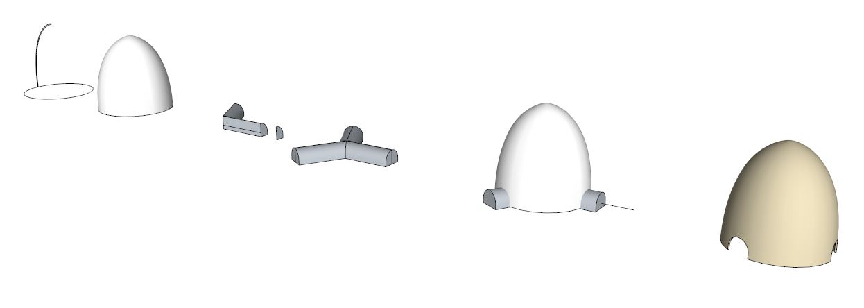
The inner surface of your nosecone is a mess and the inner and outer cones are in separate groups (so they wont join anyway). You could either re-create the inner cone as suggested above. Or if you wanted to fix it up you need to:
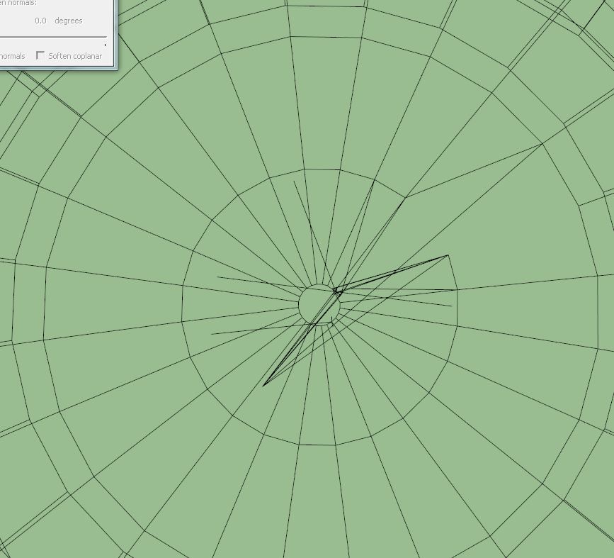
- select everything and explode
- select "all connected" and turn smoothing down to nothing (also deselect 'smooth normals')
- view in wireframe mode.
With some orbiting it is relatively clear to see which edges in the inner cone are wrong. Even some of your concentric circles on which the inner cone is based are flawed, so you need to recreate this framework before stitching the edges together. The best way to get the cutouts for the props is to create use the "intersect with model" approach.
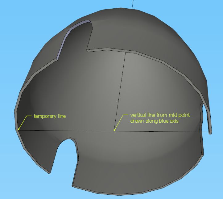
To get the axis of the propeller shaft (or something parallel to it, which I think is your second question) I would (in a separate group so the geometry doesn't merge)
- draw a temporary line between opposite corners on the base
- draw a line from the mid-point of this crossbar vertically in the blue axis direction
Cheers
- Mick
-
RE: Creating topo from CAD (.dwg) file w/ spot elevations
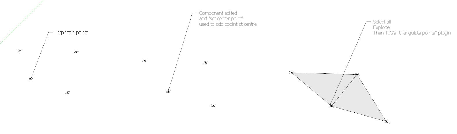
thanks TIG, yes it relies on the imported points actually coming in as instances of the same component... which I'm not sure would happen. In any case, what I envisaged was as shown here... you would copy and group the points/components so the originals could remain.
Cheers
- Mick
- Mick
-
RE: Creating topo from CAD (.dwg) file w/ spot elevations
Another thought...
If each elevation point marker is actually an instance of the same component, wouldn't it be possible to just edit one of the components to have a guide point at the centre. Then in theory all the markers have guidepoints. Select all, explode the whole thing and then triangulate? I was initially assuming that the markers were not component instances.
Cheers
- Mick
-
RE: New Member with a query...
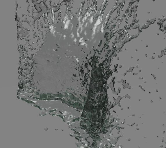
Or maybe you could try the fluid simulator in Blender (free download). The attached is a low-res version of two balls of water colliding. You could modify the effect by having them washing over an invisible obstacle of the right shape. Not sure if it is the shape that is important or the render/lighting?
-
RE: Creating topo from CAD (.dwg) file w/ spot elevations
Hi Jeremy, I haven't got the solution... but a few thoughts:
@jeremystrucco said:
file that has spot elevations x,y,z axis
.
I'm taking it that this means that the points are in correctly placed in 3D space?How many points are you dealing with? Is it feasible to manually add construction points at each autocad point? (then use triangulate points). There is a plugin at http://www.smustard.com/script/CenterPoint that will provide a construction point in the middle of your selection (you would have to select each point marker separately). I wonder if there is a plugin out there that will locate multiple centre points (1 for each connected entity within a selection)? Are all of your point markers separate from each other? or do they overlap?
I guess you've already figured out it would be easier if you had the x,y,z data as a text file so you could use the import cloud/triangulate options, but I'm assuming this isn't available to you?
Are you able to post the autocad file?
Regards
- Mick
-
RE: Air flow plugin or simulation
It sounds like you're talking about cfd modelling? There is one plugin I've come across called Khamsin which uses openfoam.
Cheers- Mick
-
RE: Copy a polyline(s) and offset
To copy or move a polyline, just select it and use the move tool. When you move it, you will be able to type in the amount of offset (e.g. 20').
However, this probably isn't what you want. If you are replicating half a tower, make one half a component (select it and right click), then duplicate the component, scale it by a factor of -1 to mirror it and then join it onto the original. Components are similar to autocad blocks.
What sort of tower - a lattice transmission tower? A picture would really help
Cheers
- Mick
-
RE: Modeling roads on a terrain
Gaieus - thanks for the tip: I've always wondered about this !
Bntheman - very good. that's basically it, just a bit different towards the end.
Pilou - I didn't use shape bender, but this would work just fine in my example as well - just goes to show how versatile sketchup is !
I'll add a few more tips:
- use the top or bottom view with parallel projection to draw your road alignment, using your terrain contours as guidance to get a respectable alignment with the right radius on your road corners.
- make sure the terrain is in a separate group to the road alignment, so that when you drape it onto the terrain, it will still be separate
- after you lift the road alignment back off the terrain, you can inspect it for places where the vertical transitions are too steep. Swap to a side on view. Replace steep dips and humps using the pencil to get the right radius for all curves. (it will now approximate, but be a smoother version of the terrain profile)
- draw your road cross-section (including footpaths, etc. if desired) at one end of the alignment, make sure it is orientated exactly perpendicular to the alignment at this point. Now use the follow me and keep plug in to extrude the section along the full length of the alignment. This plug in stops the road section twisting as would occur with the normal follow me tool.
- finally stamp your completed road onto the terrain. Peter - the width of the batters is controlled by the horizontal "offset" that you type in as you use the stamp tool, and the elevation to which you stamp it. Unfortunately, there's no simple way that I know of to control the slope of the batters (e.g. to keep at a constant 1 in 3 grade), but it wouldn't take much to edit the really steep bits if needed.
Regards
- Mick
-
RE: Modeling roads on a terrain
Another thing to add is that the approach I took is very similar to the approach you would take in something like autocad civil3D, and the results aren't a whole lot different.
In autocad speak:
- definite a plan view alignment
- get the surface profile
- modify the profile to your specifications to get rid of dips and bumps
- define a road cross-section assembly
- combine the alignment, modified profile and assembly into a finished road corridor.
I'm not a road engineer by the way, but for some reason seem to have to draw the odd road or two!
Cheers
- Mick
-
RE: Modeling roads on a terrain
Hi, see my post, which is number 11 on this page http://forums.sketchucation.com/viewtopic.php?f=79&t=40331&start=15. I hope this helps
- Mick
-
RE: Draw curved line so difficult in SU
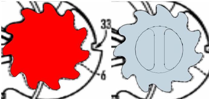
It's not too hard in sketchup. There's a few plug-ins like bezier curves. I did the following:Created an 11 point polygon
Created a tooth component that joined two of the polygon points (so each tooth would match exactly using the polygon sides for correct orientation)
rotated (with copy x10) the tooth from one point of the polygon to the next using the centre of the polygon as the axis
exploded the components and used the weld plug-in to make it a single polylineand it's regular, and you only need to edit one tooth to get the whole thing perfect
Cheers
- Mick
-
RE: Ordered my new computer
@utiler said:
Great Mick, Ta!!! Loaded it last weekend and its pretty slick!!!
Good to hear ! I don't think you'll regret the 3930K and I bet you are already impressed with the SSD ! My 2 machines have been going flawlessly now for quite a while. Not so much sketchup work at the moment, but heaps of autocad. Pretty keen to get into another sketchup project soon.
Cheers
- Mick
-
RE: Ordered my new computer
Hey utiler ! sorry, I only just saw your posts here... I guess you've got your new computer now - how's it go?
Cheers
- Mick
-
RE: See lenght instead of factor when scaling.
When you scale you can type in a dimension to scale to: start scaling, then type in 500mm (or 3m, 6" or whatever) and the axis you're scaling will be sized to that dimension. Search for a scale tool tutorial and you'll see other variants for uniform scale etc using shift and/or control. Not sure if there's any options to just see the length as you manually scale though.
-
RE: Creating a river ?
@pbacot said:
I have another. For working by sections. This requires placing cross sections (all from resizing one shape) and skinning the result. You can reshape the cross sections before skinning to account for shallows etc. Actual placement: might be good to draw lines across first to decide where sections go. Question is what gives a model that can look like real river conditions. This one comes out looking like a skate park.
Nice! curviloft seems to do a better job than sandbox. I think one of the key criteria for a river is to have shallow inside bends and deeper outside bends, and of course some natural variability! So my original example trying to extrude a standard cross-section probably wasn't the right way to start! Cheers - Mick
-
RE: Creating a river ?
Jean and pbacot, thanks - I had thought of the contour method and I agree it does give the best control and realism. I did have a play with the sandbox tools, but not creating from contours - which was a bit of an oversight ! I think a combination of this with some added detail from artisan would give the best result.
What actually started me on the cross-section thing was an idea in the back of my head that I would use the cross-sections later for some simple hydraulic modelling (eg HECRAS), but I think for my current interest the best way is spending some time making up the desired contours and then adding detail. I guess I can always extract some cross-sections later (I would use a number of section faces which I would then intersect with the model - unless anyone has other suggestions?).
thanks again for your replies
- Mick
-
RE: Creating a river ?
Thanks everyone for your replies... Sorry for the delay in my response - got called away unexpectedly !
It's not a specific river I'm trying to create - just a natural looking one, but within a defined planform (i.e. between the left and right bank lines). I'm just testing things at the moment, but what i was aiming at eventually was creating examples/visualisations of potential river restoration options and was keen to see what techniques might be applicable.
Cotty - thanks for your tip, that actually works quite nicely with my example.
Solo, I like the look of yours - it even has levee banks !
Pilou - looks funny, but in practice not too bad as the variability in the width of the river won't be as much, so the depth variance will also not be as extreme.
This all gives me some avenues to explore further.
thanks
- Mick
-
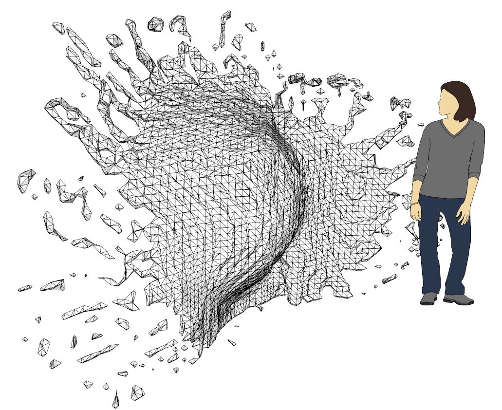
Creating a river ?
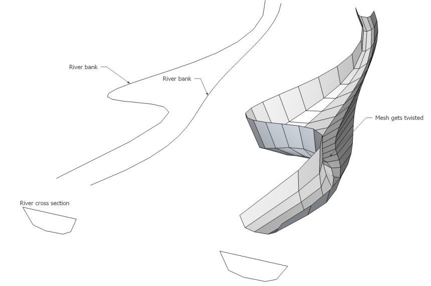
Can anyone think of a way to model a convoluted 'river' that has a variable width and depth?
Ideally, I'd draw a polyline for the 2 banks of the river, then extrude a standard cross-section along these rails.I was playing around with extrude by rails, but the mesh twists as it goes around tight bends, but what I would like is that each cross-section is perpendicular to the "centre-line" of the river.
thanks
- Mick
-
RE: New Year, New computer....
Hi utiler... I added an update on my build at http://forums.sketchucation.com/viewtopic.php?f=72&t=45071&p=414555#p414555, partially in response to this thread but thought it probably belonged better there.
Cheers
- Mick