Creating topo from CAD (.dwg) file w/ spot elevations
-
Creating topo from CAD (.dwg) file w/ spot elevations
Hello everyone, I am new to Sketchup (3-4 months) and have run into a problem. I need to make a topo surface (Of existing hillside) that I can place my model onto. I have a CAD (.dwg from my civil engineer)file that has spot elevations x,y,z axis(located in 1 of 20+ layers)but no contour lines. Can anyone please explain how I get these spot elevations into a topo surface?
I have tried messing around with "TIG Triangulate Points plugin" but no luck.
I imported CAD file in Sketchup
Deleted all layers leaving only the layer with spot elevations (Layer 0)
Attempted to use plugin on spot elevations - received "No Guide Points in the Selection!"
Noticed spot elevations were actually circles w/ lines in them
Attempted to edit spot elevation (component) to a guide point (this is where I am stuck)
I hope that once all 163 spot elevations are converted to "guide points" the plug in will work.not sure if I am even started in the correct direction. please help

-
Have a look here, and see if it helps you out.
http://sketchucation.com/forums/viewtopic.php?p=237955#p237955 -
Hi Jeremy, I haven't got the solution... but a few thoughts:
@jeremystrucco said:
file that has spot elevations x,y,z axis
.
I'm taking it that this means that the points are in correctly placed in 3D space?How many points are you dealing with? Is it feasible to manually add construction points at each autocad point? (then use triangulate points). There is a plugin at http://www.smustard.com/script/CenterPoint that will provide a construction point in the middle of your selection (you would have to select each point marker separately). I wonder if there is a plugin out there that will locate multiple centre points (1 for each connected entity within a selection)? Are all of your point markers separate from each other? or do they overlap?
I guess you've already figured out it would be easier if you had the x,y,z data as a text file so you could use the import cloud/triangulate options, but I'm assuming this isn't available to you?
Are you able to post the autocad file?
Regards
- Mick
-
Get the engineer to give you a TIN or other mesh?
-
Assuming that these 'markers' [i.e. CAD-blocks that are now SKP-component instances] are located at the correct 'elevations' [z-values] then you need to add guide-points at each one, so these can then be used in a tool to generate a mesh...
You say you have isolated these 'markers'... which is good, it makes selecting them easier...
Firstly check that 'Guides' are set to be visible [ticked] under the View menu, or in the current Style...
Select all of the 'markers' and copy/paste/run [+<enter>] this this one-liner into the Ruby Console:m=Sketchup.active_model;s=m.selection;a=s.to_a;s.clear;m.start_operation('x');g=m.active_entities.add_group();g.name='GPTS';a.each{|e|(c=g.entities.add_cpoint(e.transformation.origin))if e.respond_to?(;transformation)};s.add(g);m.commit_operationIt makes a group named 'GPTS', and adds guide-points at every selected marker into it. It is one step undo-able.
Now you can select and edit the group [perhaps using the Outliner and double-clicking on 'GPTS'] and then Edit>Select-all [Ctrl+A], and then you can use my tool to make a mesh from the now selected guide-points...Incidentally, if one 'marker' is used consistently and its origin is NOT at its crosshairs [use Model Info > Components > Show Component Axes... to see this] - to fix it... Select one instance and context-menu 'Change Axes', relocate the axis at the crosshairs as needed; note that this change won't affect any of the placed markers' locations, BUT it will then place guide-points at the crosshairs when you run the one-liner later...
-
Another thought...
If each elevation point marker is actually an instance of the same component, wouldn't it be possible to just edit one of the components to have a guide point at the centre. Then in theory all the markers have guidepoints. Select all, explode the whole thing and then triangulate? I was initially assuming that the markers were not component instances.
Cheers
- Mick
-
Sketchymick's idea is indeed a clever one...

However, you would need a guide-point [cpoint] making plugin to be able to add one to an instance, and then remove its geometry. Also it assumes that they are all instances of the same definition...
You would also need to select all of the instances once they are swapped to be guide-point ones, and then you would need to explode all instances into guide-points so that they can be used in mesh making. Selecting these new guide-points later would also be more tricky as they are not 'grouped'.
So it is a destructive solution - at the end the 'markers' are gone forever... -
thanks TIG, yes it relies on the imported points actually coming in as instances of the same component... which I'm not sure would happen. In any case, what I envisaged was as shown here... you would copy and group the points/components so the originals could remain.
Cheers
- Mick
- Mick
-
After you edit the component and add a centerpoint, before exploding all the instances, delete all the geometry of the edited component (thus all of the instancing) leaving the component content a single guide point - otherwise all those small pieces of geometry will remain in the model as stray geometry which will cause all sorts of issues later.
@sketchymick said:
...it relies on the imported points actually coming in as instances of the same component... which I'm not sure would happen...
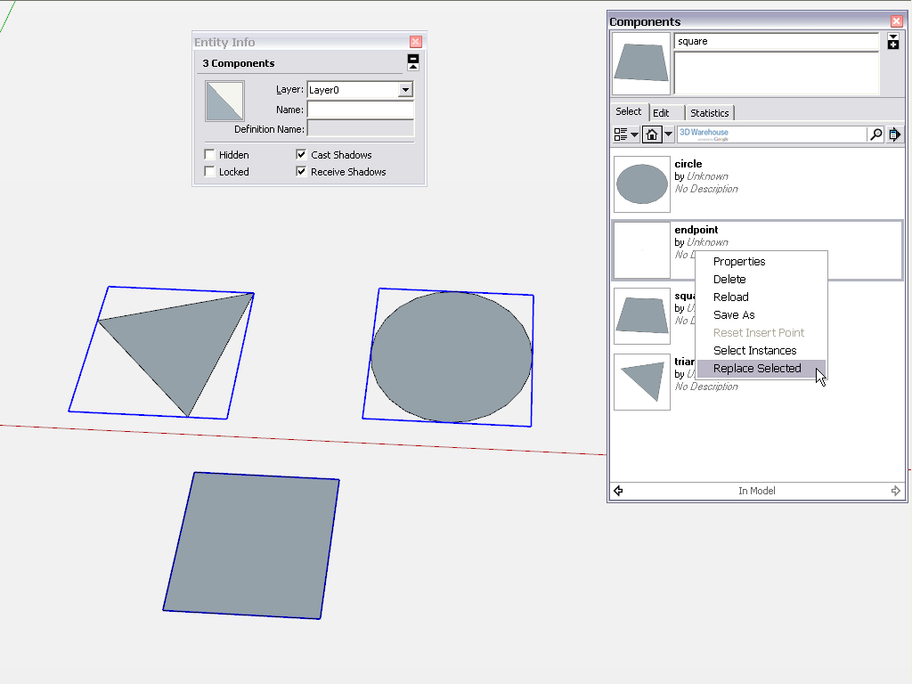
It's easy to fix it if it is not the case. First create a component with a single guide point. It will appear in your component browser just like the others. Now select all the other components (in the entity info box you can see that the "definition" is greyed out as there are three, different definitions selected) and right click in the endpoint component in the component browser and "Replace selected"...

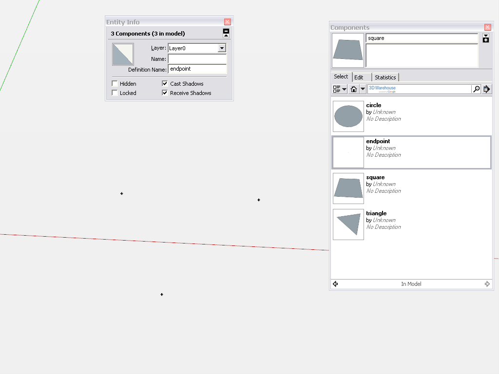
...after which you should end up with this (see that the "endpoint" definition name appears in the Entity info box showing that now all are of the same component definition):
The only caveat is if your original components component axes are not in the center of those small circles/crosses. But even that is not a big issue if they are very small as the difference will be minimal which is all right for a topo I presume.[mod=Note:kveuhw7v]I named my component "endpoint" but it should have been "guide point" - sorry for the misleading naming...[/mod:kveuhw7v]
Advertisement


