Yup, that does indeed work--and offset = .001 is close enough for govt. work.
Thanks again.
Yup, that does indeed work--and offset = .001 is close enough for govt. work.
Thanks again.
Charlie,
Aside the Stamp tool not accepting a 0" offset value, I've been unable to reliably change it to any value. It may be a SU-2013 bug. After some effort I've found a reliable kludge (contradiction?) (see screencast and attached model). What SU version are you using? Can anyone else duplicate this behavior?
Using the Stamp tool is a good solution for my tile trim problem. I'll be using it.
There've been a lot of great suggestions and I've learned a lot. Thanks to all.
@unknownuser said:
Kupono,
I think I understand your problem.....see attached file for an alternate (albeit) still basic option.Essentially........this method uses the "Stamp" function from the Sandbox tool set.
Create "stamps"..."cookie cutters"....errr....or "shears"...in this case I created 3 "cutters" to accomplish the task.....as opposed to a closed/single polygon (think doughnut) that will fail to "cut/shear" as necessary. (clear as mud?)
Once you create a proper "open/individual" stamp/cutter/shear....it is simply a matter of setting the Stamp "offset = zero" and extruding the undesireable geometry away from the desired geometry enough so that you can easily select/delete the same.
I have attached a .zip/SU file...hope it is not overweight.
Best,
Charlie
Charlie, I like this approach. I was able to extrude the unwanted areas down, but no matter what I did I couldn't get the offset to equal zero. I saw on a few older posts that the offset can not be zero so I tried .001 and then .1--neither worked. I always end up with the default 1' offset. How'd you get it to work?
@gilles said:
If you first hide what must not be cut by the section plane, it works fine.
That's very useful to know. Works great.
I initially tried using solid tools but opted out because:
each tile has to be solid and, and in my experience, solids often get unsolid, for unknown reasons, and the hunt to find the problem eats time.
you have to make each cut tile unique, then run the solid tool for each (taking a lot of time). While most of the field tile could be instances of a component saving polygons, the cut tiles would each be unique, costing polygons. I'm not sure if there will be a net savings over my single face exploded tile method.
It could be my graphics card (NVIDIA GeForce 750M), but when I rotate the model with a field of component tiles I get lags as the tile field redraws. Rotating a field of exploded tiles is smooth. This is only a minor irritation.
I thought I'd save polygons by using a single face on the tiles. They look okay until you zoom into tiles with exposed ends.
I'm going to give components another try though, now that I've discovered Zorro2. It has the ability to operate on nested components. I should be able to use the slice-model-at-section option to save time, then use solid tools for interior and oddball tiles. I'll report back.
Wishful thinking:
With Zorro2 you can draw a edge on a face of a component which becomes a cut through the component. Pretty cool. You then have to select and erase the parts you don't want. I wish it had the capability of erasing everything to one side or the other of the edge. That'd be very cool.
Cutting the tiles at the cut-planes isn't the problem. Any of the Intersect Faces options will work. It's the niggling work erasing the hairy remnants that takes time. Cotty's screen-cast illustrates the problem. Even after aligning with axis, selecting and erasing took him some time. Zorro2's Slice Model at Section options is very nice, erasing everything behind a section, but it can't handle inside areas. Checkout my first screen-cast.
Thanks for all the help.

Love the solid tools, but in this case the individual tiles aren't solids. There's only one curved face. Even if they were solid, I'd have to operate on each one individually. What I'm doing now is quicker than that.
In this case I'm cutting roof tile along vertical planes defined by the roof plane intersections. I'm currently exploding the individual tile components (non-solids), intersecting faces with context, then selecting all the various and sundry edges left over--and there are many--to delete them. Tedious work.
I'd love to find a ruby that would delete everything to one side of an intersecting plane.
Thx
Nope, no renderers, camera tools or other plugins that may affect this.
Anssi on the Sketchup forum suggested I switch from parallel projection to perspective. I did and the the rendering was instantly restored to perfect. I switched back to parallel and the rendering remained perfect. That's a mighty simple fix for a problem that's been vexing me for a while. Odd behavior though for sure.
lots of jaggiesApologies for not uploading a file previously. The problem resurfaced on a new machine. I've attached a small subset of the model with the same rendering issue.
Thx
Sketchup Pro 2013
The screen quality of a 28MB model I'm working on just went bad. It went from clean edges to jaggies all over the place with edges that should be hidden, exposed. No changes were made to the OpenGL settings, or other settings of any kind. I had just placed a section plane. It's as if the model exceeded SU's capacity for rendering. This happened to me on the same model and others before, but on an older laptop with Intel integrated graphics. In response I bought a new laptop with the following specs.
i7-3630QM CPU @ 2.4GHz
16GB ram
NVIDIS GeForce GT750M, with the latest driver: 9.18.13.2049 (openGL compatible). The NVIDIA control panel is set for application control of anti-aliasing.
With this new machine, prior to the current breakdown, the image quality was good, though there was some aliasing at close zoom. Other, smaller models displayed with excellent quality with no or extremely little aliasing at zoom.
SU installed with these OpenGL settings:
Hardware acceleration checked,
Use fast feedback checked,
#63, True Color Medium, Shadows=Yes, anti-aliasing = 0x.
I changed this to setting:
#40, True Color Medium, Shadows=Yes, anti-aliasing = 4x.
Despite the anti-aliasing difference there was no improvement in the display.
Oddly enough, once I had selected #40, #63 was no longer available. It disappeared from the available options. When I unchecked hardware acceleration and restarted, settings #101 and #102 became available, both with 0x anti-aliasing. Neither worked well. Upon rechecking hardware acceleration, setting #63 (shadows) made a reappearance along with #13 (no shadows). Neither selection helped the display, though selecting #13 made #63 disappear again. I chose setting #40 for want of anything better.
The OpenGL settings dialog is kind of a black box in which selection results don't seem to make any logical sense. It's like turning your car steering wheel right, but continuing straight, or maybe turning left. I have no idea what maximum texture size does. It had no effect on my display whatsoever.
Now for the oddest behavior.
Having some experience with this in the past with my old laptop, but with SU8 Pro, I tried a strategy that I've had success with. I selected a component of the large problem model (LPM) and did a save-as. I closed SU, then opened the saved skp file. This subset of the large model, was only 8.5MB. I hypothesized that if the LPM had exceeded some king of SU limit, this small problem model (SPM) should be well under that limit and render properly. As in the past, this was not the case. The SPM rendered with the same jaggies, exposed hidden lines and general visual mayhem as the large model had. So much for the exceeding limits hypothesis.
With the old machine I discovered that if you import a problem model into a working model, the problem goes away. So, I closed the SPM, created a new model, then imported the SPM into it. As expected, it displayed as it should. No jaggies, no weird behavior. The problem disappeared.
If it worked for the SMP it should work for the LPM, and it did. I imported the LPM into a new model and it displayed fine. That's all well and fine, but the question is why?
I believe I can conclude that:
If it's a corruption problem, what would have caused it? In this case, nothing had changed with any settings, or on the model. I had just placed a section plane when the display went wonky, though I had recently placed many section planes without any problems.
Has anyone else had this experience?
Wow, this is great! Two more tools to use in the hunt, both of which worked to find the internal face, and an excellent explanation.
Big thanks to all.
kupono
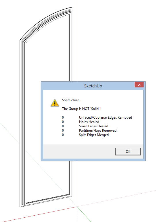
Can anyone show me how to make this group solid? I extruded a profile using the Follow Me tool. The FM tool doesn't seem to like turning sharp corners and often leaves lots of extraneous stuff to clean up.
The attached model is the result of a couple hours of cleanup and many iterations with the Cleanup and SolidSolver plugins--and it still won't go solid. I've even deleted each face to make sure none were co-planar.
I have a lot of these arched windows to do and find myself spending way too much time down the rabbit-hold chasing the elusive solid.
Thx
and mutter affirmations and incantations.
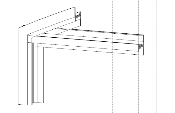
Thanks guys. Sometimes I get lost in the weeds and can't see the obvious. Even so, I wouldn't have guessed that an extra line could cause the odd behavior I was seeing, and why would reversed faces cause a problem?
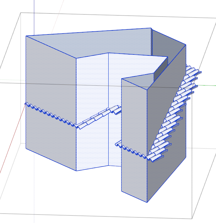
I've attached a model in SU-2013 PRO with 2 solid groups. I cannot get one to trim against the other successfully. Instead I get all sorts of inconsistent results. In fact, none of the Solid Tools except maybe the Split tool (partially) seem to work as they should.
Have I found geometry that SU can't deal with?
Guide_tools aren't working for me under SU Pro 2013. I deleted it and all the other TT_Lib related tools, then reinstalled all. Still not working.
Just yesterday pan and orbit has gone from smooth to jerky and unresponsive to the mouse.
Sketchup Pro 8
This behavior occurs in all files even a simple file containing one rectangle.
No changes were made on hardware, drivers, or the OS (Win7) prior to this behavior starting.
This is not a middle mouse button problem. It occurs even when I select the orbit or pan tool and use the left mouse button.
This behavior occurs with 2-different new mice (Logitech and MS, all drivers updated) as well as the touchpad. It happens with the non-mouse specific, HID-standard default driver as well as proprietary drivers.
This occurs no matter how I set the OpenGL settings.
There is no problem with zooming. It seems to work normally scrolling with the middle wheel.
I'm using an older laptop with the built-in Mobile Intel 4-series express chipset display adapter with up to date drivers. I know this is not the preferred setup, but it has worked fine for years without any pan or orbit issues.
Specifically, in a simple file with one object, no matter the pointing device, starting the pan/orbit with the cursor on the object, the pan/orbit works reasonably well if the pointing device motion is very slowly. The faster the movement, the more unresponsive it becomes. I'm talking about normal mouse movements here, not abrupt fast movements. The object freezes, then sort of catches up to the mouse in a large jump. I can move the cursor, at a modest speed, across the entire screen without the object rotating until I stop, at which point it it rotates with one big jerk.
This is a real pain. Thoughts?
I saved various components from the problem model and opened them individually with the same visual funk. I opened a different "good" model that didn't have the visual virus, and imported the funky model into it. It looked fine--no jaggies. I saved that component, then opened it by itself, and--drum roll please--it looked fine. Importing then exporting fixed it.
For some reason, out of the blue, the model went bad. Not only that, but all of it's offspring were bad too. The open-gl settings are the same on both the good and the bad models. In fact, the bad model was originally a component saved from the good model.