sketchucation logo sketchucation
    • Login
    1. Home
    2. kupono
    3. Posts
    🛣️ Road Profile Builder | Generate roads, curbs and pavements easily Download
    Offline
    • Profile
    • Following 0
    • Followers 0
    • Topics 25
    • Posts 88
    • Groups 1

    Posts

    Recent Best Controversial
    • Visual Problems on one model, others fine

      Using SU 8 Pro, a 1.2MB model has suddenly gone visually wacky with major aliasing. It was working fine, then it wasn't. If I open an old 20MB model, it works fine. Rebooting did nothing.

      I'm using an old machine with a built in graphics driver, Mobile Intel(R) 4 Series Express Chipset. I know this isn't a recommended setup, but it's been working fine for me.

      I had the same problem with all models using SU 2013 and uninstalled it

      What can cause a file to just go bad?


      Funky Visuals

      posted in SketchUp Discussions sketchup
      kuponoK
      kupono
    • RE: How to trace an image to create a cutout

      Thanks all for your responses. I ended up using Scan2CAD with very good results. I found that importing a raster image, converting it to a vector, and editing the vector was easier.


      Orchid Capture.PNG

      posted in SketchUp Discussions
      kuponoK
      kupono
    • RE: How to trace an image to create a cutout

      orchid.skpStill not getting this.

      In PS I select the orchid shape with magic-wand and copy/pasted it onto a new image file with a transparent background. I created an alpha channel using the Actions toolbar: Video Actions: Alpha Channel from Visible Layers action. I saved-as .png with no interlacing.

      I imported the png into SU and ran ImageTrimmer on it. It repeatedly hung SU if allowed to use ImageTrimmer-Simplifier, so I didn't. These are the results. I get a component, but it has random pixels everywhere and remains super aliased. not smooth at all like your component.


      Orchid Capture.PNG

      posted in SketchUp Discussions
      kuponoK
      kupono
    • RE: How to trace an image to create a cutout

      Thanks Tig. I'll work on my Photoshop skills.

      posted in SketchUp Discussions
      kuponoK
      kupono
    • How to trace an image to create a cutout

      Image to cutout
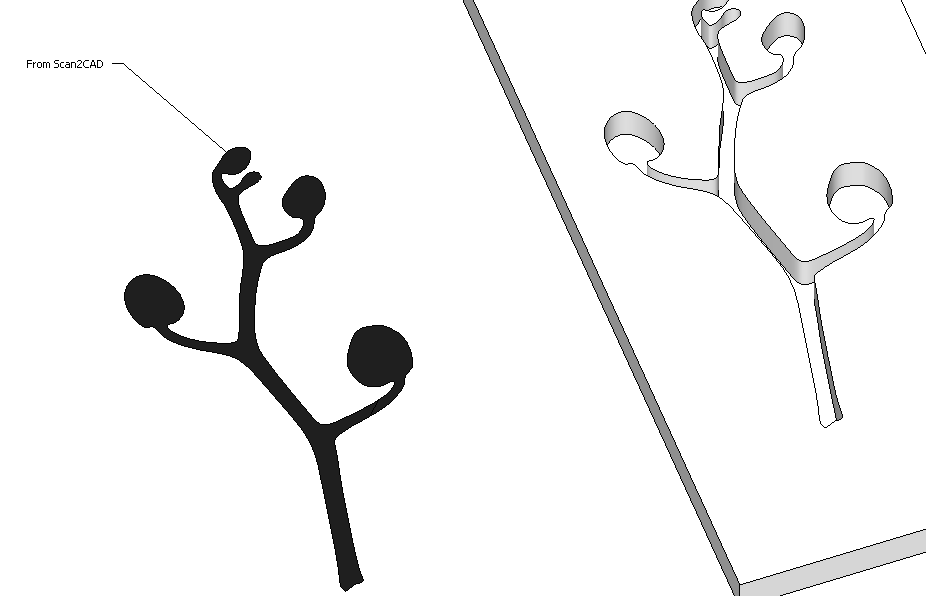
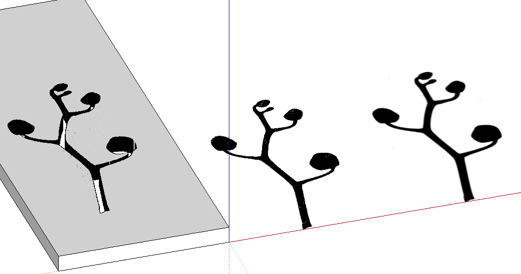
What's the best way to take an image, trace it's outline, then convert that outline to a face (cutout) that I can use the push-pull tool on?

      I've tried using ImageTrimmer with poor results. I'm not even sure what it outputs. The edges, if that's what they are as you can't edit them, are very aliased (even without using ImageTrimmer-Simplifier).Shows imported png alongside ImageTrimmer results.

      posted in SketchUp Discussions sketchup
      kuponoK
      kupono
    • RE: DC scaling screws with angles and such

      Thanks Glenn. After spending more time than it was worth, I came to the conclusion that DC wasn't going to work for me on what had become a fairly complex component. FredoScale's stretch function works very well. Although it couldn't handle stretching the entire component including it's sub-components, if I stretch the outer component, then stretch the inner components (that it couldn't handle) separately, it works fine.

      Dynamic Components would be so much better if a FredoScale like stretch function were incorporated. In fact, Sketchup might consider incorporating that function as a tool.

      Regards

      posted in Dynamic Components
      kuponoK
      kupono
    • RE: Are 'cutting components' broken in the first Trimble build?

      This gave me fits for a while. I couldn't figure out why I could get some components to glue and cut and not others. It seemed that when component axis was at a face, the cut would work, but when I tried to move the axis to the middle of the component, it wouldn't.

      Then I read Thom Thom's post:
      It's all about having a closed loop of edges on the red & green axes of the component. The blue axis must be pointing upwards.

      That is it in a nutshell. To get a component to cut through the face it's glued to, there must be a continuous edge around the component at the component's axis, which is where it will glue itself to the face.

      Thanks TT.

      Check out the attachment.


      Component glue cut.skp

      posted in SketchUp Discussions
      kuponoK
      kupono
    • RE: DC scaling screws with angles and such

      Self help indeed. Thanks for the Fredo Scale suggestion. Wow, that is quite a piece of work. Thanks Fredo.

      posted in Dynamic Components
      kuponoK
      kupono
    • RE: DC scaling screws with angles and such

      Invisible Joint: I used the the erase tool with the ctrl key to hide the edges. I learned that this both softens and smooths selected edges. Softening hides the edge, while smooth adjusts the shading of each adjoining face in an effort to make them look like one surface. This works with curved surfaces, but doesn't with flat surfaces.

      More here: http://www.mastersketchup.com/sketchup-smooth-soft-and-hidden/

      posted in Dynamic Components
      kuponoK
      kupono
    • RE: DC scaling screws with angles and such

      Okay, so I'm pursuing the strategy of breaking components that don't have 90-degree ends into multiple components that will scale properly. I've hidden the edges where they join, but the two joined faces do not look like one face. How do I achieve an invisible joint?


      Visible Joint.PNG

      posted in Dynamic Components
      kuponoK
      kupono
    • DC scaling screws with angles and such

      DC newbie here. My first project is a DC of a double-hung window. I've learned that changing a component's len(XYZ) attribute works fine for a rectangular with square ends, but plays havoc if there's an angle or other shape on an end, such as a miter, or a half-lap, or a radius, etc. It's clear that changing a len() attribute scales the component, and that everything, including, say the miter, is stretched, resulting in unintended shapes.

      This seems to me to be a major limitation. My goal for the DC was to be able to size the window component to end up with an accurate model that I could explode into a cut-list that I could build from. If I have to design the model specifically to get the DC to work, e.g. so that miters and such are in separate len() constrained components,I'm not really achieving my goal.

      I'd love to see the ability to stretch a component from a middle section so the ends remain the same. Kind of like cutting a section out of the middle, stretching it, then gluing it all back together. Actually, that's probably my best option. Create a component, such as a mitered window stop, as three sub-components; two ends and a middle. Constrain the len() attributes on the end components so they stay intact, but allow at least one axis of the middle component to scale, then set their position attributes in order to glue them all back together. Whew!

      I suppose it'd work, but I think my DC just became three times as complex. There's probably some way to do this with ruby, but it boggles the mind.

      posted in Dynamic Components sketchup
      kuponoK
      kupono
    • RE: Exporting correct scale to dwg files

      I'm having this problem too. Anyone have any suggestions?

      posted in SketchUp Discussions
      kuponoK
      kupono
    • RE: LO Dimensions offset from actual points

      Usually, but in this case I'd have some 200 scenes. I'm trying to economize.

      posted in LayOut Bug Reporting
      kuponoK
      kupono
    • RE: LO Dimensions offset from actual points

      After messing with this some I've made some observations.

      The SU scene I'm using in LO contains about 30 components that in a front ortho view stretch from left to right. In LO, I have many view-ports that each have to be panned to the components I want to display and dimension. It's how I pan that seems to affect the dimension offset.

      The problem seems to occur when I double-click the view to edit, and use the pan tool to position on a component. The longer the pan distance, the more it seems to exacerbate the offset problem.

      This seems to work though:
      Insert the SU file reference, set the scene and scale, adjust the view by first checking the preserve scale on re-size checkbox, then grab the bounding box scale grips and successively stretch one side, then shrink the other, until the view is positioned how you want it.

      So far, this is working for me.

      posted in LayOut Bug Reporting
      kuponoK
      kupono
    • RE: LO Dimensions offset from actual points

      This thread is pretty old. Has anyone come up with a solution to this problem? Let me clarify my problem. On an ortho view, when using the dimension tool, the green context dot that indicates the intersection of edges is offset from the actual intersection by quite a bit. The resulting dimension lines are likewise offset.

      I've messed with moving and stretching the viewport to no avail.

      posted in LayOut Bug Reporting
      kuponoK
      kupono
    • RE: Scene's Default Layer Changes by itself

      Excellent! I think I understand now.

      So my fundamental problem is that, though my primitives are on layer0, so are many groups and components.

      Because a Scene doesn't save the state of the active layer, layer0 may (or may not) be active and visible in a Scene, therefore all of the entities including the groups and components associated with layer0, will be visible.

      If I don't want to see them, I need to associate them with a layer that can be made invisible. So then, if all primitives remain on layer0, but all groups and components are associated with other layers, I will have visibility control over everything.

      Thanks

      posted in SketchUp Discussions
      kuponoK
      kupono
    • Locking a Page or a SU Reference?

      I can't see how, but is it possible to lock a Layout page, or maybe a Sketchup reference, so that a reference update doesn't screw up a page?

      Thx

      posted in LayOut Discussions layout
      kuponoK
      kupono
    • Scene's Default Layer Changes by itself

      I think I'm missing something fundamental with how a default layer works with multiple scenes.

      I want to create a scene that has one and only one visible layer for use in Layout, but I find that my scene's default layer changes on me, and since the default layer is always visible, I end up with two visible layers.

      For example on my test model:

      I create Scene-0 with layer0 as the default layer.

      I create Scene-1 with layer1 as the default layer. I make layer0 invisible and update Scene-1 so that it now has layer1 as the default and only visible layer. (Visible Layers is checked when I update)

      From Scene-1, if I select Scene-0--then select Scene-1 again, the default layer in Scene-1 will have changed from layer1 to layer0. Both Layer0 and layer1 are now visible.

      This behavior seems to be consistent, but I don't understand why and it sure defeats my purpose.

      Thoughts?

      posted in SketchUp Discussions sketchup
      kuponoK
      kupono
    • RE: Can't unlock nested components

      Well, it looks like exiting then reopening the model fixed the problem. I should have tried that before posting. Thanks

      posted in SketchUp Discussions
      kuponoK
      kupono
    • Can't unlock nested components

      I have an unlocked top level component with locked nested components. Context clicking on any of the locked sub-components displays the context menu with unlock grayed out. I'm pretty sure all the nested components are on same layer.

      Thoughts?

      posted in SketchUp Discussions sketchup
      kuponoK
      kupono
    • 1 / 1