Bonjour.
Le site d'Abvent semble maintenant fonctionnel.
Salutations.
Bonjour.
Le site d'Abvent semble maintenant fonctionnel.
Salutations.
Hi folks.
This is probably very basic but, when I click submit, in my personnal message box, the messages are put in the outbox and remain there. Nothing is sent. What button shall I press to actually send the messages ?
Best regards.
Hi CWatters, hi folks.
If you really dont want to orbit untill you are looking more horizontally than vertically, just draw your rectangle on the horizontal plane and then rotate it by 90° around one of its sides to make it vertical.
Just ideas.
Hi Arvmehta, hi folks.
Double click the component to enter Component Edit Mode (CEM) or right click and choose "Edit Component" in the contextual menu. When in CEM, use SketchUp (SU) tools as you would on any geometry. Click outside the component bounding box to exit CEM. This also applies to groups.
Just ideas.
Hi folks.
I have not been able to get to the Abvent forum at this address since at least last friday (march 7 2008):
http://www.abvent.com/support/forum/
In fact, the whole site seem unaccessible.
Artlantis site seems in the same state of non availability.
As of today (march 11 2008), both sites are still not responding.
Best regards.
Bonjour.
Depuis plusieurs jours, je ne peux plus accéder au forum en Français sur le site d'Abvent à l'adresse suivante:
http://www.abvent.com/support/forum/
En fait, le site au complet semble être non disponible.
Quelqu'un a-t-il une idée ?
Salutations.
Bonjour.
Une fois qu'un objet a été assigné à un calque, tu peux contrôler la visibilité du calque pour voir ou non l'objet en question. Le menu Fenêtres --> Calques va te donner accès au gestionnaire des calques pour te permettre d'en ajouter, de les supprimer, de les rendre visibles ou non, etc.
Tu peux aussi créer des Scènes (Pages avec SU version 5 et précédentes) pour mémoriser tes réglages.
Par exemple, tu pourrais créer un calque appelé "Cote". Tu pourrais assigner ce calque à toutes les cotes de ton modèle.
Puis tu crée deux Scènes. Une nommée "Avec cotes" et l'autre "Sans cotes". Le choix des noms est à ta discrétion. Sur la scène "Avec cotes", tu rend le calque "Cotes" visible. Sur la scèbne "Sans cotes" tu rend, évidemment, le calque "Cotes invisible.
Ne pas oublier de faire la mise à jour de chaque scène après quelque changement que ce soit (visibilité de calques, changement de style, visibilité d'objet, mode de rendu, etc) si tu veux conserver les changements.
Salutations.
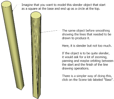
Hi Outersketcher, hi folks.
Draw your cross section, as shown in your picture.
Pull it to required length (the developped length along the curve).
Scale one end down symmetrically about the center using any of the corner handles.
Cut the model along its length with equaly spaced cuting planes.
Delete the planes.
Bend the result along the curve.
See my tutorial on "How to make a horn" in the Modeling section.
Just ideas.
Hi folks.
I know it is obvious but to make simple steps quickly, see the attached SU file for ideas.
Hi Stevie, hi folks.
To actually cut, you need a real rectangle drawn with SU tools, not a Section Cut rectangle made with the Section cut Tool.
To cut objects, I often use a circle as a cutting plane since it is easy to "force" its orientation (red-green plane, blue-green plane or blue-red plane or any already available surface, vertical, horizontal or even slanted) and lock it with the SHIFT key. Once the circle is drawn, I move it on the object and then do the cut.
Just ideas.
Hi folks.
You can also use the Text Tool. The default text is:
X,Y,Z coordinates for end points;
Length for lines;
Area for faces;
Name for components and groups (if named, otherwise "Group" will show as the default name).
Just ideas.
Hi folks.
If you want to print a 8 cm line as 8 cm on paper, you use a 1:1 scale.
If you want a 1:20 printing scale, your real life 8 cm lines will prints as 4 mm on paper.
Draw the line in real size (8 cm).
Select any of the standard view.
Disable perspective.
Now, in the Print Dialog box, you will be able to specify the scale used for printing. For example that 1 cm in model is 1 cm on paper (1:1 scale) or 20 cm in model is 1 cm on paper (1:20 scale) etc.
As for scaling when drawing, it may be required when modeling very small objects. For that I simply set my units to meters and pretend that they are millimeters. For exaple, I need to draw a line of 2 mm. I enter 2 in the VCB. SU will interpret this as 2 meters (2000 mm). After my model is completed, I simply scale the model down with the Scale Tool by a factor of 0.001. Since SU will not accept this number, I do it in two steps using 0.1 then 0.01 or the reverse.
Read the help about printing, more specially, the Printing to Scale chapter.
Just ideas.
Hi folks.
I know it is obvious but just in case.
With exploded circles and arcs, you can use this procedure:
1 - Draw the perpendicular from the midpoint of two adjacent segments. TWo lines to draw.
2 - Their intersection point is the center of the circle.
Just ideas.
Hi folks.
On SU for Windows (SU 6.4.112), the angular precision can be set up to 0.001°.
On SU for Max OS X (SU 6.4.120), the angular precision is maxed out at 0.1°.
Why this difference ?
Best regards.
Hi TheDuke, hi folks.
You may easily test if any endpoint is not on the intended plane by using the Text Tool.
This tool has the interesting property of proposing default text that often serve useful purpose. On an endpoint it will gives you the X,Y and Z coordinates of the point. Boost the unit precision to the max (0.000001) and you can see if any point(s) is (are) not on the same level as the others.
The tool propose the following default text for these objects:
Endpoints : X,Y,Z coordinates
Lines : line length
Faces : area
Groups :"group name" if the group is named, otherwise "group"
Components : "component name" if the component is named, otherwise "text"
Just ideas.
Hi folks.
Of course, my idea is for lines that may be skewed with all three axis.
In the meantime, see attached SU file showing the three methods I have found so far.
Hi folks.
While answering a question in one of the other SU forums on Google, it occured to me that the Circle Tool could behave as the rotatet Tool to allow to draw a circle perpendicular to a line.
The procedure could be like that :
1 - Select the Circle Tool.
2 - Press the left mouse button (LMB) anywhere on the line (endpoint, midpoint, inferenced point, whatever) instead of clicking to position the center of the circle.
3 - Slide the cursor along the line to make the circle perpendicular to the line.
4 - Release the LMB to set the circle orientation.
5 - Move the cursor to set the circle radius (typing it in the VCB if required.
Just ideas.