Well, I appreciate whatever you do find in your investigations.
It seems there is so much that can be done with SU/Ruby, but then othertimes SU/Ruby seems to have voids.
Regards, John
Well, I appreciate whatever you do find in your investigations.
It seems there is so much that can be done with SU/Ruby, but then othertimes SU/Ruby seems to have voids.
Regards, John
Hi TIG:
I understand your response.
I already do make several scenes.  But with geometry relatively close to together (piping, pumps, valves, etc.), tight clearances(an area where section cuts are particularly useful), its configuration and with different presenters working on the same project and design elements changing at the last minute it can be a real challenge. Plus the fact that the presenters (often lead engineers) are usually VERY casual users of SU and don't use it at all in any depth.
The presentations are with a client (not the public or a broad audience) and deal mostley with discussions regarding preliminary design options. In the most simplistic situation ("John, I know your busy but I need this done in 15 minutes...."), 3 or 4 planes could be set up and the presenter could use the the tool to "pan" to specific areas that were not anticipated when the Scenes were established.
My thought was to provide them with an easy and flexible means of manipulating the model view in order to quickly respond to specific questions asked of them.
Regards, John
I was tinkering a bit with section planes and came up with this approach. It would probably be difficult to manage, but in some instances I suppose it could be useful.
Draw an line or some other geometry. Pick the Section Tool and snap it to the edge(s) and make the Section Plane active. Select the edge(s) and the Section Plane and group them. Pick and choose other edges and section planes, and repeat the process.

I was watching an inhouse presentation of some design concepts being proposed.
I had set up predefined sections for specific scenes as well as some scenes where the presenter could toggle on and off specific sections for any view. But, as always, discussions came up in which the current Section positions were not adequate.
Is there were a way to at least move a Scene's Section along its normal via the up-down cursor keys withOUT having to turn on Sections and use the move tool?. This could be very useful.
Some options for a more sophisticated script would be a persistent dialog in which:
a. the increment value could be modified (unless there could be a smooth continous movement via keeping the cursor key depressed)
b. specific Sections could be chosen and change which are active and which are not.
c. Section color and edge-thickness could be modified.
Interesting how the points are created with the attached.
The group was rotated, then the axis.
Apply an 2x2 FFD . The points kind of follow the user defined axis.
detrach:
In your .skp you mention choice "J". I don't have that listed in my PullDown menu.
Has there been newer release of the ruby or is this a typo?
As a convenience it would be nice if you could select one point and then be able to select all of other points that share the same x, y, or z plane.
First thing comes to mind is press "B" for the Blue plane, "R" for the Red plane, or "G" for the Green plane. Also, Ctrl-click another point to add another plane of points or Shift-click to Add or Subtract a plane of points.
Jim,
Been try to decipher this thread. Looks like a convenient way to organize/reorganize scipts.
Would you mind summarizing "how" this works (in general terms), how to install and modify?
J
Ah, Didier, that is even a more efficient way to assign tranparency.
Also, I use groups on just about everything and once you are inside a group the the display of bitmaps "behind" may not be viewable.
Thanks for the tip, Alan.
Think being able to adjust the opacity would be worthy for the SU7 Wishlist?
Thanks for the reply, but I needed to adjust the opacity while drawing in SketchUp, not for output.
I am photomatching and the current opacity hides too much of the photo.
J
Anyone know if there is a way to modify the amount of opacity used in the X-Ray mode?
John
Gata:
" ... if you softened the out-of-bound mesh from a Sandbox-made grid, then it's one face to select for deletion."
This tip will help be out significantly!
I will have to download Soap Skin Bubble and install it on my new PC. I had forgotten all about it.
Thanks, again.
John
Thanks, Chris. It looks like a practical interface/approach.
If only ONE point were selected, then is the "stretch" done relative to the opposite point on the same plane or relative to the center of the 9-point plane?
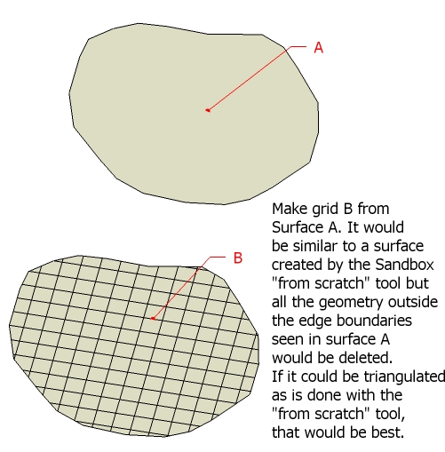
I have a huge site area for which I may have to produce a surface from contours. Since it is so large, the fewest possible contours will probably used.
In certain areas, close to structures, more detail may be added. I was hoping to create a From Scratch surface (see the sandbox toolset), project the boundary edges of the focus area onto the From Scratch surface, do an intersection, and erase the surfaces/edges which lay outside the boundary. Then use the Smoove tool to do some surface shaping. However, the step where the out-of-bounds geometry is erased is a painstaking process.
I was wondering if there is a script that could create a grid from a selected surface and automatically trim of the excess; even better yet do the triangulation bit that the From Scratch tool does?

SU Follow-ME and many of the scripts that have been written can create some very awesome geometry.
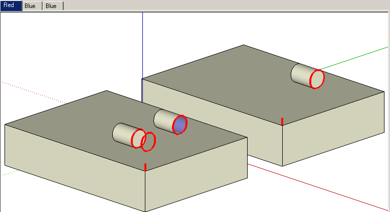
However, the properties of native circles and arcs are lost as they are kloned, moved, rescaled, and/or rotated; ie., when a circle is Follow-Me'd along a curve.
The conveniece of using the Entity Info properties (for example the Radius property) is no longer available for the derived geometry, which can make subsequent modications to geometry more difficult.
Couldn't a script be developed that could analyse a model or a selection (and all its nested entities) of all Non-Circle and Non-Arc geometry which are comprised of coplaner segments which are equal in length with equal angles at their vertices and then "redraw" them as Circles and Arcs?
Regards, John
Hi Chris, as always, very impressive.
A few questions:
Are the deformations restricted to just the SU default axis?
If the group/component is rotated manually before being deformed, what determines the deformation "planes"?
Is there an ability to deform relative to a specified point, (ie., center, opposite handle, or inference point). Is there concentric deformation relative to a specific point?
Regards, John