make a copy of the drawing.
relink the model in the copy.
delete the viewports you do not want in the original.
copy and paste the viewports from the copy into the original.
not elegant, but it should update when you change the models.
make a copy of the drawing.
relink the model in the copy.
delete the viewports you do not want in the original.
copy and paste the viewports from the copy into the original.
not elegant, but it should update when you change the models.
@sdmitch said:
Took a look at both of the models posted and I'm a little confused. In the 4X? and 6X?, the two largest beams seem to be the same size but are colored differently. Also, the materials used, are they imported or picked from a materials palette?
nope, you are not confused. those last ones should have grown another 2". operator error on my part.
new models attached here.
colors were picked from the 'color by name' palette.
@dan rathbun said:
Another thot.
Could the faces in the component definitions were placed upon layers named for the width (ie, "7.5 wide",) then "Color by Layer" could be toggled on / off at will. The face "colors" would actually be layer colors ?
that is clever... would allow me to keep styles for presentation, without affecting overall model.
layers would then be 'T-8x' 'T-10x' etc.
@sdmitch said:
bmike,
Did you forget to post the model?
Yes the faces bounding box dimensions change depending on orientation in the model but that is not a problem.
sorry, got involved with family stuff over the holiday weekend.
attached are 2 models - 2014 and V8.
i have created an array of timber off to the side with colors and sizes.
depending on the client i work in either whole inch, or nominal, so coloring might get complicated in that
7.5" to 8" = green (8x timber), etc.
if that isn't possible then we can add another shade of the same color for the whole inch or nominal size.
@sdmitch said:
To bad you didn't think of this in the beginning where you could have colored the faces when you made the components but the solution seems to be simple enough. So, if you could provide a base model to test on, I'll be happy to give it a shot.
I can build 20-30-40 library components and use them... but sometimes I get AutoCAD data or SketchUp models from clients / partners... I can guarantee you that those will not be built with my components.
I'll post up a test model later tonight. Really though, all we are doing, that I cannot do as I don't code or know Ruby, is color a face within a component based on its width. Its width of course, is determined by its orientation in the model though.
I tried doing this with a dynamic component... but didn't get very far.
I have also played around with embedding dimensions into a component on a layer I can toggle on and off - but that removes the ability for the component to be a solid...
Thanks for the help!
@sdmitch said:
so the 8" wide face gets a different color that the 10" wide face on the same beam.
Yes, ideally.
Otherwise I'd need to setup a color system of gradients for the entire timber to be a specific color matched to a specific size....
@sdmitch said:
could you supply a sample model and color list?
Do you really want each individual face colored or just applied to the component which would have to be unique in either case.
Do you want a model with the colors applied? Or just a base model?
Not sure what you mean by the last part of the question.
I typically call out sizes like this "1P1 8x10" or "3G4 7.5x11.7"
The location is 1P1 (Bent 1, Post 1) and the size is 8" x 10".
So, it is really helpful to see each face colored, rather than having the entire component be the same color.
Is there any way to write a script (or build a dynamic component) that will color code individual faces of components based on their X or Y width?
See image:
Typical Model:
After plugin:
There would need to be a list of colors assigned to a range of values, and we could ignore the Z axis, as I build all my components for timber with X,Y as width and depth, and Z being the length.
Ideally I could select the entire model and let the script run. I'd hate to have to select each and every timber to make it work.
The other stipulation is that whatever solution is created - the timbers must be able to maintain their ability to be 'solid' - as I use solid tools, trim and keep, etc. for much of the joinery workflow.
Background:
Most of my work is in timber structures - I use SketchUp and LayOut primarily for shop drawings and overall design / modeling. A time consuming part of my workflow is applying labels in LO to individual components. The new leader with auto text picked up from the component is a great first start. But I don't name components by size, typically they are named based on their location within the structure.
But, what I'd like is a graphic way to easily see face dimensions via color.
If any of the plugin authors knows of a way to do this, PM me or reply here.
@dave r said:
[attachment=3:lp5xixsu]<!-- ia3 -->Screenshot - 3_28_2014 , 8_50_20 PM.png<!-- ia3 -->[/attachment:lp5xixsu]
[attachment=2:lp5xixsu]<!-- ia2 -->Screenshot - 3_28_2014 , 8_54_11 PM.png<!-- ia2 -->[/attachment:lp5xixsu]
Like this?
I see what you mean about the Bug Splat but after I gave it a logical grouping it works just fine. I expect it's caused by your strange method of grouping.
I used this plugin on an entire house - windows, doors, walls, compound roof, etc. etc.
I crashed and crashed - until I started to pull apart the model into logical groups.
After I figured that out - it worked perfectly.
To solve a 'bending' a large model - draw an origin, and a line. Now take apart the model in logical groups (all the windows, all the doors, the walls, etc. etc.
Copy / Paste in place into a new drawing the group of objects, and the origin and scale line.
Group everything, FredoScale Bend.
Copy / Paste in place into a new drawing.
Repeat, but always paste the bent components in place together, in that new 'bent' drawing.
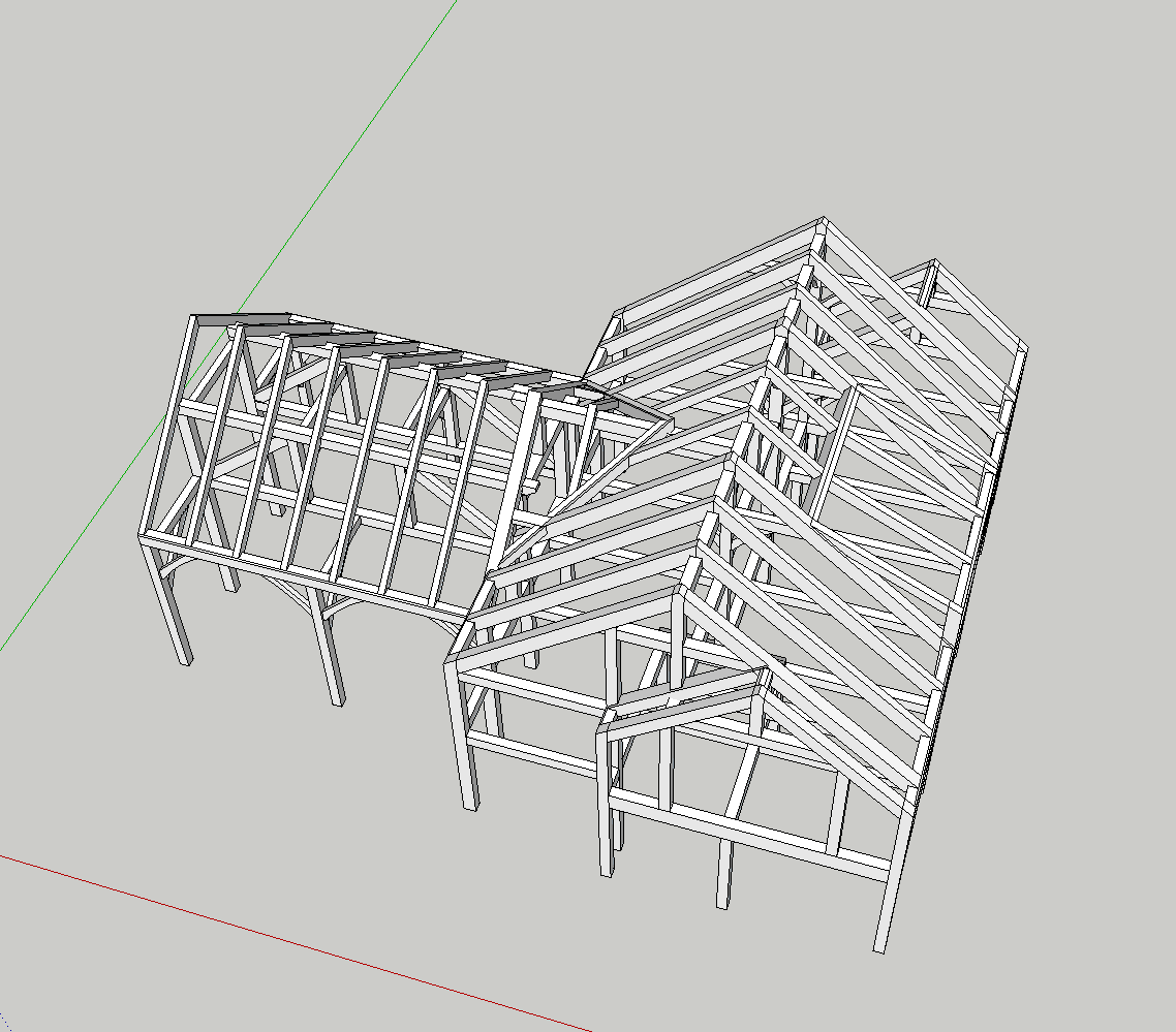
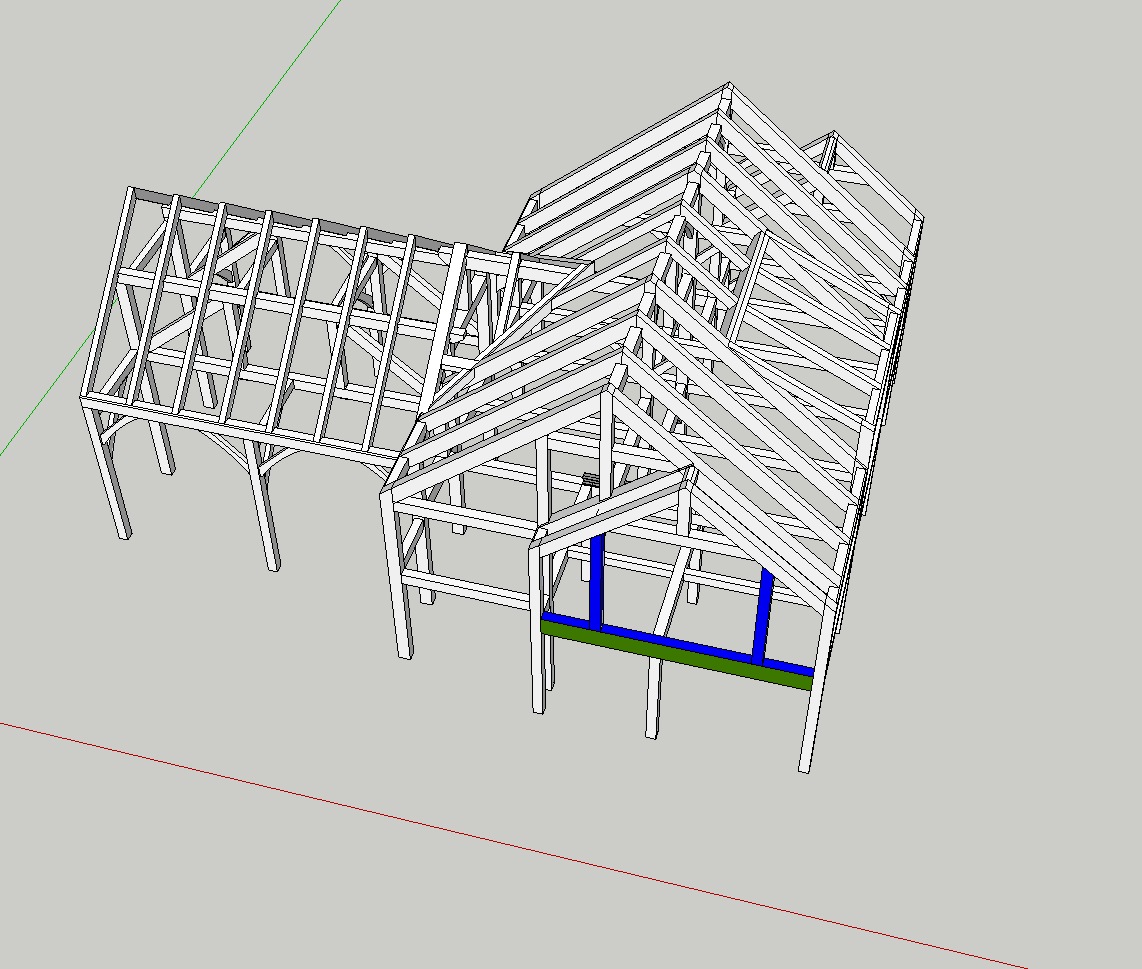
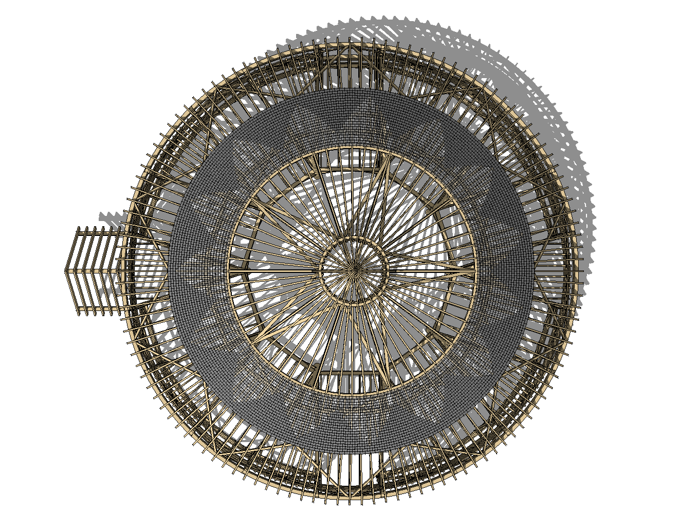
It let me take this:
[attachment=1:lp5xixsu]<!-- ia1 -->Screen Shot 2014-06-13 at 11.43.55 AM.png<!-- ia1 -->[/attachment:lp5xixsu]
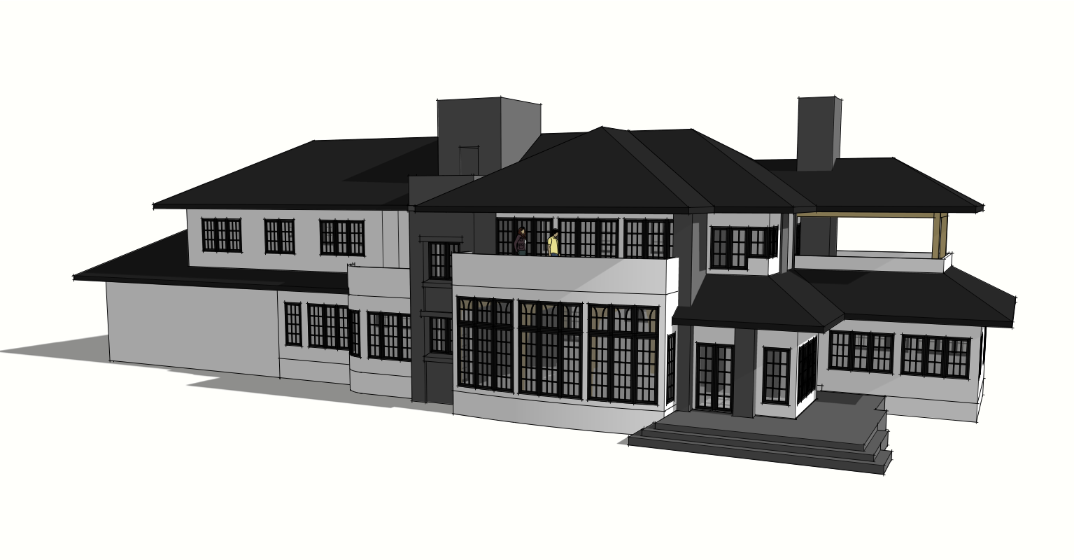
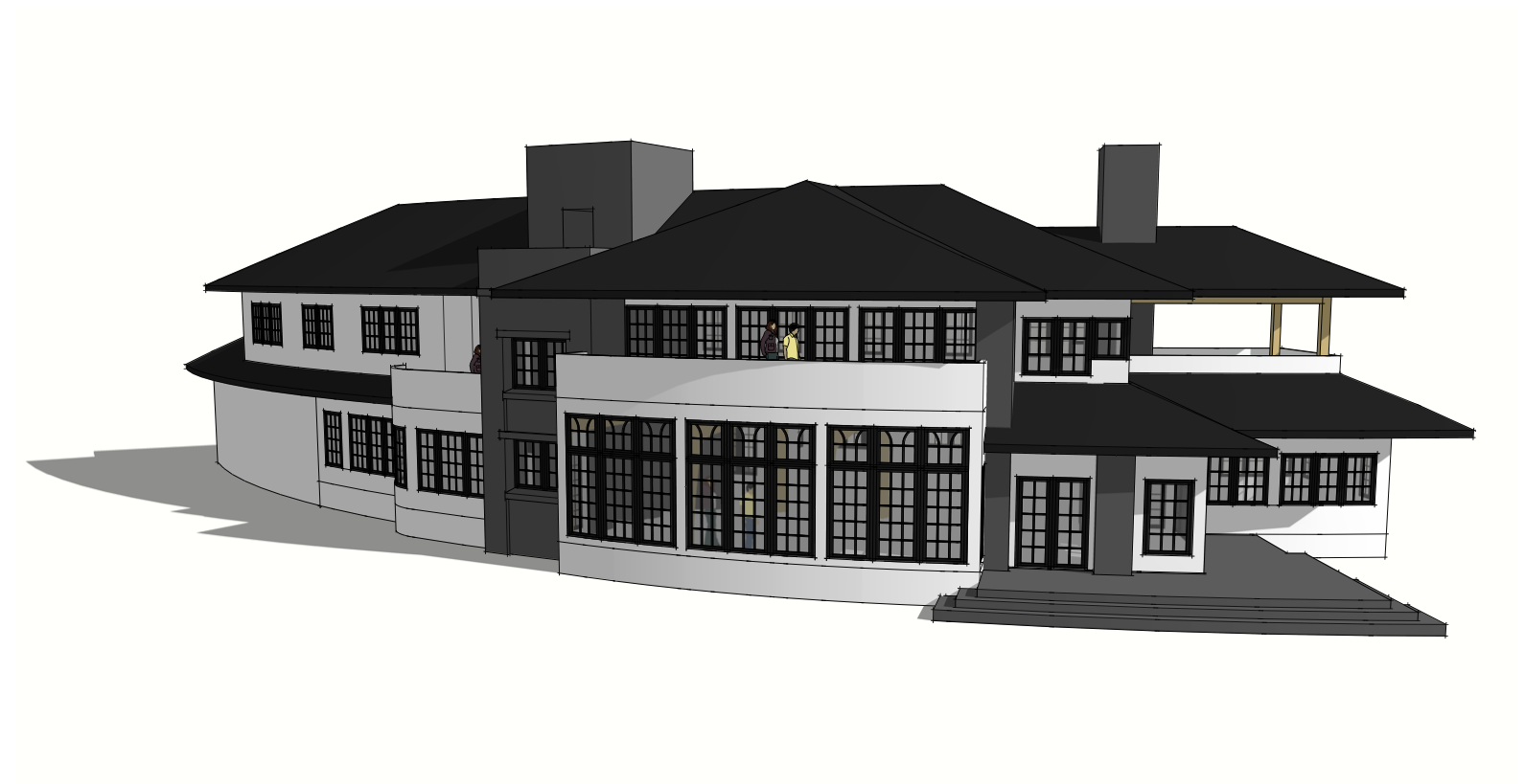
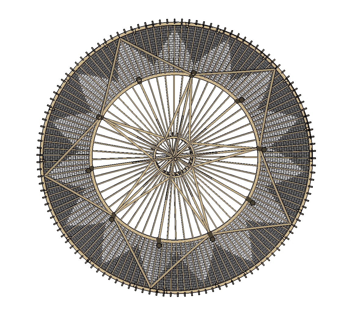
To this:
[attachment=0:lp5xixsu]<!-- ia0 -->Screen Shot 2014-06-13 at 11.43.44 AM.png<!-- ia0 -->[/attachment:lp5xixsu]
@tandem said:
So where is the documentation when you need it?
I think bulbangs' question does very much belong to this thread as controlling lines in LayOut is at the core of creating construction drawings.
yeah, but buried in here, 14 pages deep, few people, including the SU team, will ever see it.
this should be asked in a new thread, and maybe reported as a bug.
Pro, 2014 on Mac OSX ??? (latest, I keep my machine updated).
Having issues exporting out of 2014 to AutoCAD DWG (does not seem to matter what version / date).
A couple of drawings simply refused to export - the display goes silent and I do not get the Audit confirmation dialog box.
Recently, with a simpler model (all 2d linework from section cuts) I found multiple overlapping copies of the groups / sections - as well as random geometry.
I launched 2013 and V8 to export the same drawings with success.
Anyone else having issues?
deleted out all the kolbe windows and doors and its running much better now, vector, hybrid, and raster.
cleaned up all of the windows and doors with thomthom's plugin - still crashes.
so now, to figure out if its 1 bad component, or many.
I'm having serious trouble with 2014 on a project with a deadline.
My Bugsplat has also gone missing. It pops up in my current applications, but I can't access it anywhere to send in reports. I can switch to it, but get no window to send in a report.
I've had probably 20-30 crashes in the last few days getting a set of drawings out.
The drawing will crash when switching rendering styles, and now upon trying to export a plan view.
I can PM to share the model / LO file with someone from the SU team, if possible.
Mac OSX Mavericks, last update via Apple 10.9.2
Late 2011 Macbook Pro 17"
8g Ram
AMD Radeon HD 6770M 1024
2.5g Intel Core i7
@pbacot said:
That's beautiful, Mike. So inspiring while I schlog along with my residential work. Can I come and sweep your studio? Actually it really is encouraging to see this work.
Thanks!
Sweep? Ha. You'll trip over the kids toys and have to fight the dog to get in... my commute is up the stairs to my office.
Still amazed that the barn is going to be a working barn. Incredible, really, that they are doing this.
@tig said:
It is - http://sketchucation.com/pluginstore?pln=TIG_solidsolver
And it works just fine in v2014.
Many such Plugins needed no adjustment to be compatible...A simple search in the PluginStore's own Search box is a powerful ally...
Please don't move Plugins over from an earlier SketchUp version [unless you really have to!]: get the latest Plugins version that is available - some Plugins have had to be reconfigured to also work in v2014, whilst a few others still need fixing [hopefully none of mine?].
well, all that came up was your manifold plugin. but i found it. had to add a space between solid and solver. and then scroll down a bit.

thanks.
Hi TIG,
Is this in the Plugin Store?
Want to know if I should load the old one or if there is a new one for 2014...
Did they move it on the Mac? Otherwise its in Application Support...
Update on the Round Barn. Its still going up.
Can't really share much... but I've been asked to help template the slate roof.
3 different pitches.
80' dia footprint.
Tapers everywhere.
Concept below, for the middle pitch.
Getting as built conditions from the builder this week. Then will have to generate the slates.
They want to pre-cut as much as they can... over 6000 slates in the lower roof alone.
auto text! just ran through my latest project. time saver. worth the free upgrade.
will see how the performance of layout works. i tend to have 20-30 page documents, most rendered vector. with multiple models reference. hoping for the speed improvements that are touted.
downloaded, but in the middle of a large project. so... does it install over 13 like the last versions? i'm pro on osx.
i need layout to be stable... for at least the next week. despite the tease of page numbers and faster vector rendering.