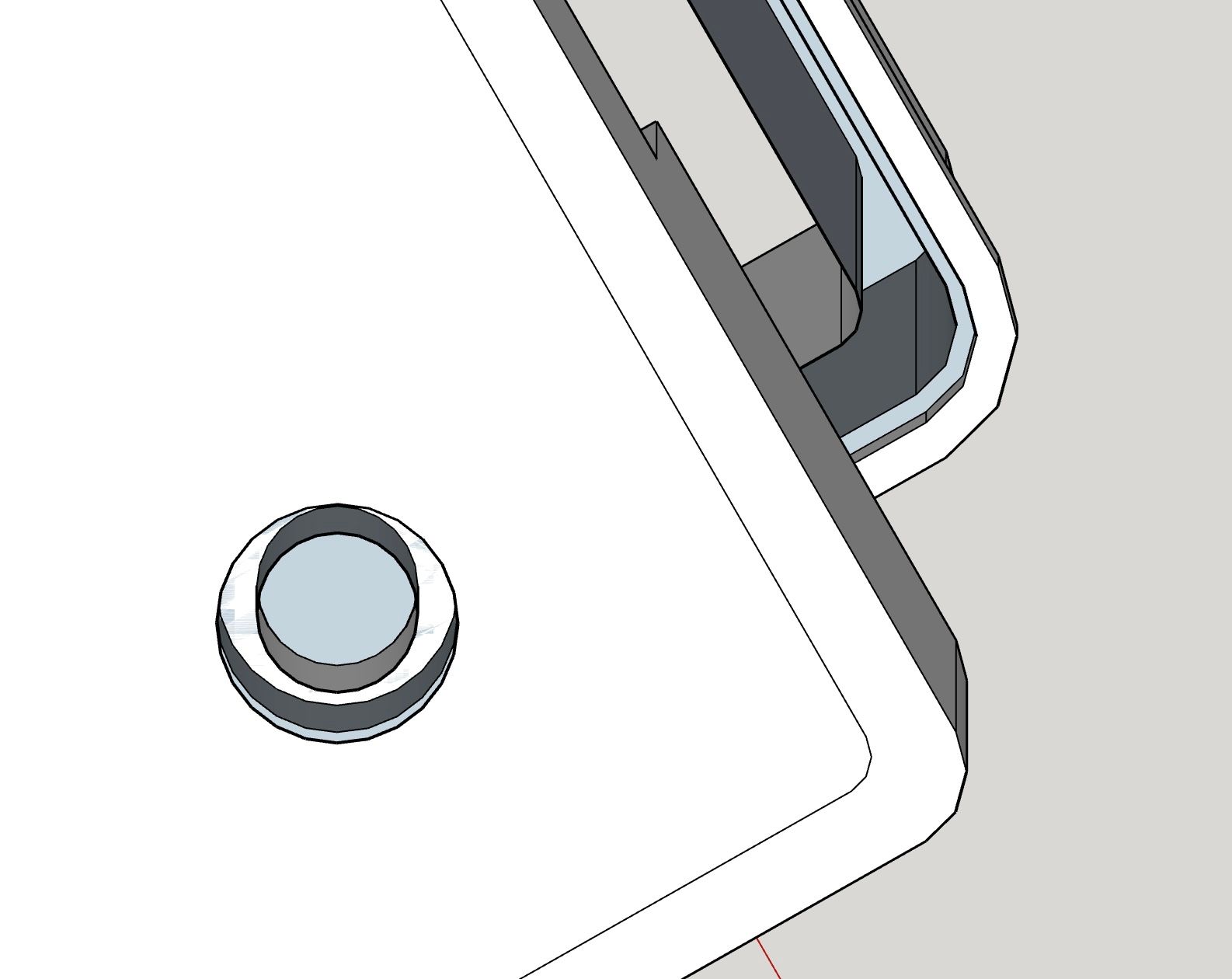
What I still don't know: how can I guide the rounding on the lid around the corner?
Posts
-
RE: Open areas and rounded surface
-
RE: Open areas and rounded surface
@Box I am reassured to read I would not be right to be crazy

-
RE: Open areas and rounded surface
@Dave-R Let's say, I was crazy, until I opened the eyes.
How can I remove the sectioning? I have never used this function (like many others!). -
RE: Open areas and rounded surface
Sorry, but there was only 1 file attached here, from you 2 days ago, and you removed it, I assume, because it is no longer in your post.
The file I downloaded, 2 times, hence the number 2 after the name (which also indicates that it is the downloaded file), contains only my drawings, unlike the one shown by @Box in the gif posted earlier. And he (or she) didn't post an SU file!
Am I crazy or am I right?
Update: I have found the file below the image, of which I first thought it was the name.
So, everything is fine! Sorry
-
RE: Open areas and rounded surface
Far be it from me to contradict you, but when I look at the parts from below, I think I see open surfaces. Sorry.
By the way, it doesn't matter, but my drawings are not in your file

-
RE: Open areas and rounded surface
You have attached an SU file. You must not have drawn everything (?), because there are also open areas under the holes and at the bottom edge of the lid in this file.
-
RE: Open areas and rounded surface
Thank you very much for all the work you have done!
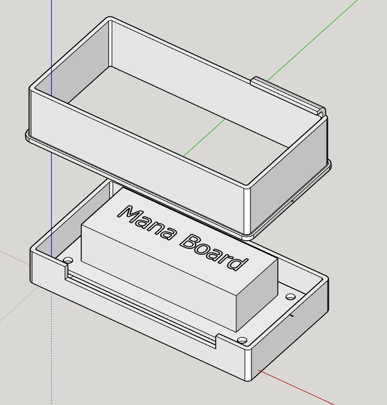
It's actually not that complicated if you proceed as in your video.The text is not printed; it just gives this block, which represents the ManaBoard with its structure, a name.
-
RE: Open areas and rounded surface
Rather strange that some people have that button, other people don't.
The link to my SU file:
-
RE: Open areas and rounded surface
@Dave-R I don't have that button!

-
RE: Open areas and rounded surface
@Dave-R said in Open areas and rounded surface:
it's very difficult to understand the problems in your model from a single screenshot
That's sure, and therefore I wanted to join the file but I didn't find how, as I already wrote in my initial message. I only found an icon to join an image, but not a SU file.
-
Open areas and rounded surface
Hello,
I would like to 3d print a box to hold a mana board, with an elongated opening for the cables.
On the bottom of the box there are 4 holes for fixing.
Viewed from below, there are open areas in these holes that I cannot close.
Idem for the underside of the lid edge.What is also missing is the top of the lid, because I don't know the exact height needed yet, but also because I don't know how to draw a rounded surface all round. In the attached SU file (update: I don't find how to join the file), there is the beginning of a curve at the edge that ends at a corner because I don't know how to continue the curve over the corner.
How can I close the open areas? How can I complete the curve?
Doesn't the construction also have to be "filled" somehow so that it can be 3D printed?
Thanks in advance for any help!
Aloohaa
-
SU crashes when exporting as .dxf file
Hi,
Recently SU crashes every time I try to export an object as .dxf.
I have tried 3 times.Is there a known solution for that problem?
Incidentally, there is a problem with this object that may have something to do with the crash:
there are 2 holes in it. When I look at it from above, I can only see one hole; I have to rotate a little in space to make the second one visible.I then copied the object into a new SU file: I can see both holes and the export also works!
Update: now, even if I close SU normally, I get the message that it has crashed!!
Kind regards
Alohaa -
RE: Constructing a box with swallowtail joints
Thank you for your comments and suggestions.
I made these connections some time ago and you can only see the radii if you look at them from close up. They do not bother at all. And these parts are very small, compared to my current project.
I am doing this with a 3mm router, so the radius is 1.5mm, which will not bother you at all.

-
RE: Constructing a box with swallowtail joints
@box said:
It would also be a pretty straightforward job just using arrays, and perhaps solid Trim.
If I knew how to do!
@dave r said:
No. They aren't dead.
They are all dead except that one to contact the seller.
I sat down and drew simple tooth connections by hand. In fact, the true swallowtails are quite difficult to make on the mill, because there are non-rectangular angles on one side and I would have to resort to 3D machining, which is quite complicated in Estlcam, the programme I use to make the G-code.

-
RE: Constructing a box with swallowtail joints
"Lathe" is not the correct word, I meant a CNC mill.
On the linked website the links in the Purchasing section are dead!

-
RE: Constructing a box with swallowtail joints
"Something like this?"
Yes, except that the tails should have the same dimension as the "holes", but I think that is a matter of settings!?
As I said before, I also need to divide the sides in height, as they do not fit on my lathe as a whole, and the parts also need to be joined together.
-
Constructing a box with swallowtail joints
Hi,
I want to make the sides of this box with my CNC lathe using swallowtail joints; the sides are 500mm high and the swallowtails should be 25mm wide.
I also need to divide the sides in height, as they do not fit on my lathe as a whole, and the parts also need to be joined together.
I have started to draw this by hand, but it is very time-consuming and complicated.
Therefore my question: Is there a possibility in SU Pro to make this easier?
Kind regards
Alohaa
-
RE: 18 instead of 1,8
You are right! If I press the K key they disappear!
An interesting function, discovered by accident. -
RE: 18 instead of 1,8
Hello,
I've started from 0 again, haven't encountered this problem until mow, and don't remember exactly what I did, so I can't reproduce the situation; the dynamic components are a very difficult thing (much more complicated than in Onshape, for example).
I drew a beehive without dynamic components first, with a wall thickness of 19mm.
In this context I am interested in the dynamic components to be able to change the wall thickness (the dimensions inside remain the same), which has an influence on other components (the corner mouldings in the attached skp file for example), whose position changes with the change of the wall thickness.
In the tutorial I followed, this is simpler: a simple shelf in which all parts have the same wall thickness; this is not the case in the beehive, where the inner wall is thinner, for example.
In the case of the shelf, the wall thickness is defined in the main component shelf, which is not possible in the case of the beehive.
I had the idea of adding a small cube to the shelf component that has the same dimensions as the wall thickness, but I can't work it out.
How should I proceed? Where can I find an explicit instruction or a recent tutorial adapted to the current SU version; the one I followed is from 2014?
In the attached file is also the shelf (whose side parts have disappeared; I probably deleted them unintentionally) and steps, both following a tutorial.
As of this morning, there are dashed lines in the beehive; I've never seen that before. This represents the lines of the parts that are not visible. Could it be that I switched this on without meaning to? Where?Kind regards
Aloohaa


-
RE: 18 instead of 1,8
Since nobody has replied any more, I assume that there is no explanation and that I will have to save the file and open it again; at least a solution for the problem with the measurement (happened to me again this morning).
I can forget about the dynamic components, which I regret: I'm about to draw a hive and want to be able to vary the thickness of the walls.
