Nice surprise to go away into the Ontario wilderness for a week's canoeing, and come back to find a problem has been raised and resolved without my doing anything. Thx, all!
Posts
-
RE: [Plugin] Lamella Roofs
-
RE: [Plugin] Lamella Roofs
Hi Dave R,
My understanding from this exchange is that the problem was related to Victor Hugo's plugin folder, but is there anything I should do to make this plugin more robust?
-
RE: [Plugin] Lamella Roofs

I've updated the plugin to allow the creation of a diagrid lamella roof, where the lamellas are co-planar, following brookefox's suggestion, and to add some error-checking and spinners on input. Updates are located with the original post.
Under some circumstances the upper surface of the lamella is not created properly, for reasons I still don't understand. The cutting instructions are correct, regardless.
-
RE: [Plugin] Lamella Roofs
I've corrected the plugin to reflect the very helpful community comments, and fix some minor errors in the way curved surfaces were being generated. Both the revised plugin and documentation are embedded in the original post to make them easier to find.
I'm still puzzling over a couple of issues. First is the odd failure of the intersect_with method in at least one circumstance. (Posted elsewhere http://forums.sketchucation.com/viewtopic.php?f=180&t=46714). This wipes out a couple of faces in a lamella, but is rare, and easy to fix manually. Second, the geometry is off by a small (< 1mm) amount in terms of the components not lining up exactly. It doesn't feel like a rounding error, so my calculations may be incorrect. Practically this is not significant.Thx all, and TIG and Thomthom especially, for your advice.
-
Intersect_with problems
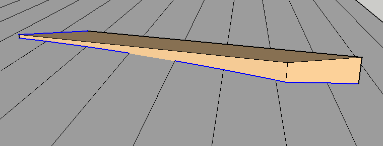
I've been using intersect_with to find the intersection of a cylinder (a group) and a prism (another group), where the prism is skewed relative to the prism. In some, but not all, instances the method drops an edge. Here's a pic:

The intersection breaks when you try it manually as well -- easy to fix, but rather undermines the idea of a plug-in! I'm attaching an abbreviated model.
Any ideas??
-
RE: .edges returns a face
I reinstalled SU and the problem went away, so it looks like TIG was correct. I'll have to check my backups to see what version of SU was running (it would have been current, though). The profile info was obsolete.
-
RE: .edges returns a face
@tig said:
BUT
face.edgesdoesn't return a face, it does return an array of edges.
face=Sketchup.active_model.selection[0] #<Sketchup::Face:0xef75e64> face.edges [#<Sketchup::Edge:0xf0a8b10>, #<Sketchup::Edge:0xef75e78>, #<Sketchup::Edge:0xf0a8c28>]
or
face.edges.each{|e|puts e} #<Sketchup::Edge:0xf0a8b10> #<Sketchup::Edge:0xef75e78> #<Sketchup::Edge:0xf0a8c28> [#<Sketchup::Edge:0xf0a8b10>, #<Sketchup::Edge:0xef75e78>, #<Sketchup::Edge:0xf0a8c28>]
Are you using the standard Ruby Console ?
Do you have any other tools that might ill-advisedly mess with the base-classes likeSketchup::Face?
Your installation is most likely 'broken'
Have you considered reinstalling ?Yes, it's the standard Ruby Console.
No, I have no other tools that mess with the base-class.
I'll re-install and see what happens.
Thx for the feedback. -
.edges returns a face
I can't figure this one out. Here's the output from the Ruby Console:
back
#Sketchup::Face:0x1cbbfe74
back.edges.each{|e| puts e}
#Sketchup::Edge:0x1cbc1850
#Sketchup::Edge:0x1cbc1a1c
#Sketchup::Face:0x1cbcfc84
#Sketchup::Edge:0x1cbc0cc0
[#Sketchup::Edge:0x1cbc1850, #Sketchup::Edge:0x1cbc1a1c, #Sketchup::Face:0x1cbcfc84, #Sketchup::Edge:0x1cbc0cc0]How can the .edges method return a Face?
-
RE: Draw a new component with axes at original pick point?
@tig said:
A hand built component always has its axes at the bottom left of the component's bounding box.
You can of course change it at the time of creation or later on using the context-menu.
A group is similarly axis-ed but there is no adjustment to the axes manually later...
To use code to change e.g. a group's axes you need to work out the transformation needed to move the group back to the model-axes, oriented as desired, and then apply the same transformation.inverse to the group.entities so the contents are moved back to where they appeared in the model before, but of course the group#s axes [aka its insertion-point] might well be in a different place and/or the group itself might be rotated in 3d too...Thx, Tig -- this is helpful. But what does "hand built" mean? The example I cited was a component built in code. Contrast this example:
` ents = model.entities
Build a parallelogram centred on the origin
a = ents.add_line([-75,-25,0],[25,-25,0])
b = ents.add_line([25,-25,0],[75,25,0])
c = ents.add_line([75,25,0],[-25,25,0])
d = ents.add_line([-25,25,0],[-75,-25,0])
d.find_faces
shape = ents.add_group(d.all_connected)
shape_as_component = shape.to_component
shapedef = shape_as_component.definition
dummy = Geom::Transformation.new()
ents.add_instance(shapedef,dummy)`Here the new instance is located with its corner at the origin, not overlaying the original. Hence my confusion.
-
RE: Draw a new component with axes at original pick point?
I was hoping this discussion might resolve an issue I've been wrestling with. I created a group at some odd angle and position in a model, and then turned it into a component (group.to_component). When I created a new instance using an identity transformation it showed up in the same place (which is what I wanted).
brace = brace.to_component
braces = ents.add_group()
dummy = Geom::Transformation.new()
braces.entities.add_instance(brace.definition,dummy)
In this case the component instance and the component definition seem to be in the same place
brace.bounds.corner(0)
Point3d(-94.3149, -12.7862, -48.5601)
brace.definition.bounds.corner(0)
Point3d(-94.3149, -12.7862, -48.5601)But in another example I have a component created the same way, but the component origin (i.e., the corner of the boundingbox is relocated to [0,0,0]. In this case a new instance is created at the origin, using an identity transformation. How does SU decide, when it creates a component, where to place the origin of the component definition?
-
RE: [Plugin] Lamella Roofs
@watkins said:
Dear Tim,
You and your colleagues are to be congratulated on your achievement. How long did it take start to finish, and did you have building experience before starting the project?
Kind regards,
BobThx Bob,
This is actually a one-man show. I built a lamella roof (the one shown at the top of the thread) some years back, based on a crude, and actually wrong Excel model, but only worked out the exact geometry last year. Writing a plugin involved learning Ruby (OK, it shows!), and grappling with the SU documentation, which I have to say I find opaque in many ways. The plugin probably took about three months to work out.
I'm not a builder at all, but I've done some simple construction work, if dry-stack walls count.
-
RE: [Plugin] Lamella Roofs
@brookefox said:
Will the routine allow the creation of in-line lamellas, without the slight offsets?
Thank you much for sharing, Tim.
(bmike, you didn't forget the bookmark feature here?)
Simple answer, no. The plugin assumes the use of dimensional lumber and common bolt connectors, as in the original Zollinger concept, and in recent examples like the Rural Studio dog shelter http://apps.cadc.auburn.edu/rural-studio/Default.aspx?path=Gallery%2fProjects%2f2006%2fhalecoanimalshelter%2f. But it's a natural option, and easier to model. Thx for the (implicit) suggestion.
PS I'm attaching a brief monograph on the underlying geometry.
-
RE: [Plugin] Lamella Roofs
To be precise, a section through the roof across its axis is circular, but the lamellas are skewed, so the edge is elliptical. However, to complicate things, there is a twist in the elliptical surface. If you run the plugin and inspect the lamella closely you'll see how it works.
Nervi designed aircraft hangars in this style. Also Junkers (of dive-bomber fame) designed a steel lamella system used by the British in WWII for over 100 hangars in RAF airfields scattered across the UK.
-
RE: [Plugin] Lamella Roofs
Indeed, a beautiful roof. Note though that this uses the Cowley connector http://www.cowleytimberwork.co.uk/connectors.htmlto line up the lamellas at the nodes, which is a bit fancy (and may be expensive). There are quite a few modern examples of lamella roofs, and I'm going to document them on my blog (http://www.lamellaroof.com - so far unpopulated; stay tuned!) I personally like the through-bolts, and the offset look.
-
[Plugin] Lamella Roofs
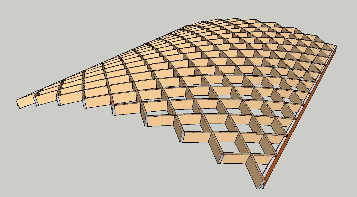
A lamella roof is made up of many identical lamellas arranged in intersecting helical arches. It looks like this:
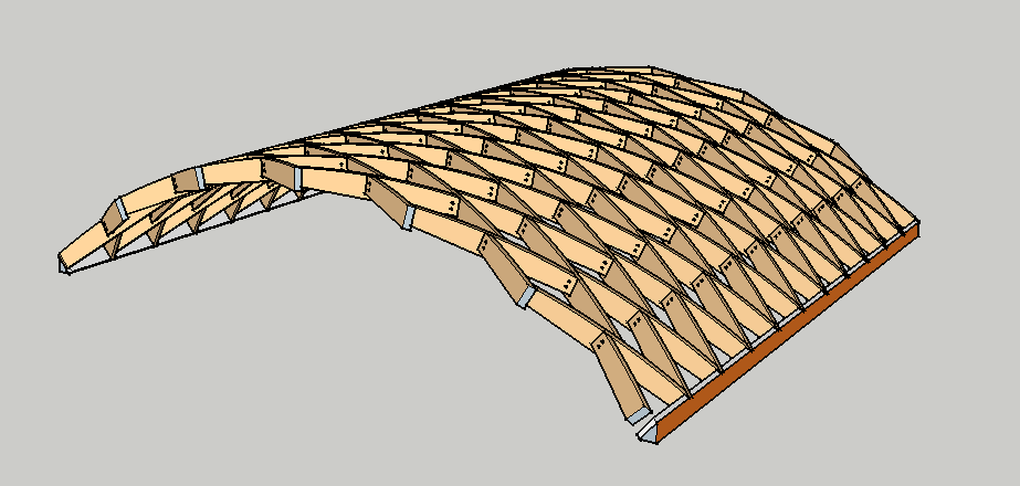
I have created a plugin that generates a Sketchup model of such a roof, like this:

The plugin also supports the creation of a diagrid roof, where the lamellas are more-or-less co-planar, rather than staggered.
The lamella_roof plug-in and documentation are attached. All comments very welcome.
-
RE: Erase_entitiies crashing SU 8
Thx ..my carelessness in thinking a vertex was a drawing element! .../T
-
RE: Erase_entitiies crashing SU 8
Thank you, people. This works. I'm still a bit confused about the issue of drawing elements, because when I tried deleting the vertices entity collection (which would have the effect of removing the whole component instance) SU still crashed. But the vertices object only contains vertices.
Tim
-
Erase_entitiies crashing SU 8
I have a piece of code that crashes SU 8 (on a Mac).
Basically the idea is to create an instance of a component, find the positions of its vertices and then erase the instance. The instance is created correctly; the vertices are correctly printed, but then SU dies. Here's the code fragment, where ents is model entities.
brace_template = ents.add_instance(brace.definition,brace_transformation)
bte = brace_template.explode
vertices = bte.select{|e| e.typename == "Vertex"}
puts "Brace coordinates"
vertices.each{|v| puts v.position}
ents.erase_entities(bte)
Any ideas why this is happening?
-
Automatic edge-breaking?
I'm trying to use Ruby .add_line to add an edge to a surface broken into an upper and lower face by a curve. When I use add_line to add a single edge, top to bottom, the edge isn't automatically broken by Sketchup, which I thought was the default (Sketchup.break_edges is certainly "true"). What's the solution? (It's a bit tough to figure out where the new edge would cross the curve, so difficult to add two edges separately.)