@ntxdave said:
Here is the other file that did not get uploaded before.
Maybe the 3rd try will be successful...........
@ntxdave said:
Here is the other file that did not get uploaded before.
Maybe the 3rd try will be successful...........
Here is the other file that did not get uploaded before.
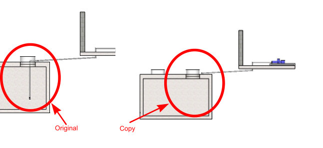
I drew a set of tanks that I wanted to include in another SKP file that is eventually used in a LayOut document. When I include the original drawing in the "consolidated" file that will be part of a large LayOut document, the original item is not showing up correctly in the "consolidated" file. I have included an enlarged view of the problem as can be seen in the jpeg file. I am also attaching the two SKP files.
I would appreciate some insight into what is going on. I feel that I am going to be doing a fair amount of this and need to understand what I am doing wrong.
Water Reclaim - Tanks Below Ground.skp
@ntxdave said:
If I am brave enough, I will post some of this stuff when I am done (give you a good chuckle for the day).
OK, here is what I wound up with.
@box said:
That's not the greatest image in the world to get the full picture. Can you give something with more of an overview to understand better what it is, or something with more detail. I'm guessing it's a pipe fitting with a tap but I'm somewhat worse for the whiskey just now, been a long day.
Yes, it is not a good image. The yellow part at the top of the picture is where the lower part of the coupler screws on the faucet. It goes around the pipe "sot to speak" You gave me a good enough idea though that I think I can go draw what I need.
If I am brave enough, I will post some of this stuff when I am done (give you a good chuckle for the day).
@box said:
Show us an image of what you want and I'm sure we can tell you how.
Something similar to this.........
@box said:
One simple way is to use, 'Make Unique Texture'.
You can paint your whole concrete slab with whatever material you want. Then right click on the top surface and select make unique texture and click ok. This gives you a new material in the in model section of the material browser that you can edit.
So everything has the same colour/texture etc but just the top surface is see through.
Thanks Box, that gave me exactly what I was trying to do. One of these days, I am going to learn how to do this stuff so I can start giving back to the forum.
Now if I could just find some nice easy way to make some connecting pieces for some of the pipes. I have looked at a couple of plugins but seems like the only ones that have the capability I am looking for are a little on the pricy side but I will keep looking
Once again, thanks for giving me those instructions.
I have an object in my model that I have colored with a material. Now I want to make the material on a section of the object partially transparent. If I select the material that I used and adjust the transparency, it does it for the entire object. I only want a section of the object to be somewhat (not entirely) transparent.
There must be a way to make a copy of the material and then adjust the transparency of the copied material and then just apply that material to the selected area. I so not want it to be 100% transparent or I would just delete the face for that give area. I want the use to be able to "see through" the selected area because there are items that I want them to see but I want them to understand that they are "inside" the selected area.
In this case, I have a piece of equipment that is buried in the ground but has a piece that goes from the buried object to the surface. I want them to be able to "see through" the ground and see the part that comes up to the surface.
Hope that makes sense to everyone.
@watkins said:
SpaceClaim is very powerful, and is taking on many established 3D modelling programs (Inventor, Solidworks etc). If you have a connection to academia (lower and higher educational institutions) then it is very cheap. You can also import Sketchup models and turn them into editable solids.
http://www.spaceclaim.com/en/SketchUp.aspx
Regards,
Bob
Yes, I saw that page. I was wondering if you can get just the part to clean up the STL files and what the pricing is. I saw one placee on the web tha the full product is about $$3,500.
The video on that page makes it look like it is very powerful at the STL file clean up.
@ben ritter said:
What about making the slab a semi-transparent material?
I may try that but in some situations I cannot do that for other reasons.
@tig said:
If you preselect things and right-mouse-click you'll get a context-menu.
The contents of that context-menu vary with selections etc...
If the object[s] selected is/are a '2d-styled-line'... then there is an item in that context-menu 'Edit 2D Line Style' [there's a similar item if you have selected some 2d-text == 'Edit 2D Text'].
Select the Edit option and the Settings dialog opens.
Change the settings and OK
The selected 2d-styled-line[s] change to suit...
Thanks.....I was making the mistake of clicking on the tool, selecting the new setting and then clicking on the line I had previously set the style for. What a fool. It is so easy when someone shows you the silly mistake. Does exactly what I want and I am also able to move that line to another layer so I can now put different line styles on layers with the appropriate scene so I am off to the races (well at least I have a much better understanding of how to move closer to my desire).
Now if I could just draw the pipe and then change the edges to the desired line type, that would be really great. I see that SMUSTARD has a similar tool. It would be interesting to see if their Profile Builder would allow me to develop a Profile using my own line style.
Thanks again for your assistance. I think the documentation for the tool could be a little better but this may open more doors for me.
@tig said:
To change a preexisting styled-line select it and use the context-menu item to edit it...
What do you mean by the context-menu item? I suppose this makes me look kind of stupid
@ntxdave said:
@tig said:
2dTools LineStyler can make some dotted/dashed patterns ?
Or use LayOut ?I will "mess" with it some more and see if I can control it better
OK, I can move the line to another layer so I can control whether it shows up in a particular scene but I am having a problem if I try to modify it. As an example, I set the LineStyle to 5.0 Dashed Red and I would like to change it to 1.0 Dashed Blue. I assume I am doing something wrong but I do not see how to modify it. Also, if it is a curved line, I see segments and would have to modify each segment.
I also assume if I want the dashes to be spread a little farther apart, I would have to make my own pattern with different spacing.
Since my goal is to show/indicate objects that cannot be seen directly (like a pipe), I will have to draw multiple lines.
I also use Profile Builder a fair amount, it would be neat if I could draw objects (like my pipe and some other items) with that tool using dotted/dashed lines. It would seem to me that this type of capability would be used a lot in a tool like SU but maybe that is my "newbie" or "uneducated" background coming out.
@tig said:
2dTools LineStyler can make some dotted/dashed patterns ?
Or use LayOut ?
I have used the plugin a couple of times but have had a problem trying to understand how to use it consistently. It also adds layers that I find mildly confusing. In particular when I want some things to show up in different scenes.
I will "mess" with it some more and see if I can control it better
I need a method for showing/indicating the presence of pipes under a concrete slab. Many architectural drawings show them with dashed lines. Anyone have a clever trick for accomplishing this?
Anyone every heard of or used SpaceClaim to clean up or prepare STL files for 3D printing? Also, their web site does not mention pricing.
@richard said:
BTW, if the rectangle isn't a clipping mask, make it up of two grouped horizontal lines and two grouped vertical lines and 4 ungrouped arcs. That way you can scale all to the radius you want and then select two arcs and move them to the bounding size you want and scale the lines back to join. This will be really quick!
Thanks for the reply. In this case, I was just designing a template so it was not a big deal to just redraw the rectangle. Just wanted to know if I was missing something. Seems like a bit of a shortcoming in the product to me. Not a show stopper though.
Is there a way to adjust the radius of rounded corners in rectangles is LayOut without redrawing the rectangle?
I have drawn a rectangle with rounded corners but would like to adjust the radius of the corners and not completely redraw the rectangle. I have searched the knowledge forums and various tutorials and I cannot find a way to do it.
@dave r said:
You can set the LayOut project to any paper size you want in File>Document SetUp>Paper. It has nothing to do wiI regularly work with paper sizes I can't print on my home printer.
I went to Print Set Up in the Print section. Will I ever learn?
@dave r said:
Did you look under Preferences>Extensions to make sure the box for Round Corner is ticked? Did you look for its toolbar?
How did you install it? Did you use the SCF Plugin Store to do that?
All is working now.......