Thanks guys, I think Ill try the 99$ one to start. They both look pretty good from their website....
Posts
-
RE: Shader Light vs Twilight Render - which is better?
-
Shader Light vs Twilight Render - which is better?
Hey guys, Ive been gone from this site for almost 2 years now and I know alot has changed in sketchup land... (I guess I qualify as a "newbie" poster again lol) Im looking to buy a simple renderer plug in and Im looking at Shaderlight and Twilight as affordable options so far - they both look simple and good. However - I use a TON of custom 2d 'face me' components that are created using png's that have a transparent background (even though in SU I cut along the edges so I get some type of shadow silloette....). I was wondering if either of these renderers support the transparency. IF you have any other suggestions for other programs go for it! Thanks

-
RE: Modeling from plans
@unknownuser said:
This is how I do all my architectural models Pete. If you ever need me just give me a shout...
I wish that after you extrude the floor plan that there was a way to "project" the linework elevation onto the sides of the building. Mabee drape could work???? I tried this method shown above a couple weeks ago...still kinda a pain, I ended up placing components on the elevations - scaling the windows ie to fit, then placing them on axis by moving the individually.
-
RE: Modeling from plans
@unknownuser said:
@unknownuser said:
tracing over all those lines and then pulling them upwards is tedious
Why do you need to trace? All you have to do after you bring it in is use the 'MakeFaces' ruby. It doesn't work all the time but it does fill in most faces so you don't have to trace that much to get the faces...
It also depends on who did the drafting. I sometimes find that some people don't close there corners or intersections which can be very annoying but you have to make sure everything is good in AutoCAD before importing into Sketchup. IMO, that can be the most tedious part...
YOU GOTTA USE THE "LABEL STRAY LINES" AFTER YOU USE MAKE FACES.... IT SAVES LIVES! I also find it very useful to select all geometry and intersect selected, that picks up alot, even though SU7 is supposed to do that automatically, I find it doesn't.
-
RE: AUTOCAD import woes - any architects out there?
@gaieus said:
You can try an easy trick: select all in your model and make a component (hopefully there are no unnecessary,stray lines miles away). Now the component will have its own axes - as close to the component geometry as possible (i.e. at the corner of the bounding box).
Now export this component as a SU model (right click > save as), open it, work on it and all and if you need the original placement, go back to the original model, right click again and reload. You can even explode the component now if you wish.
hmmm.. that sounds like a neat trick. Does that mean all the coordinate data will be reletive to the component axis and the only million feet away coordinate would be the one defining the location of the component? Ill keep you posted next time I get a chance to try it out. My only concern is how and if LandFX will be able to read the relationship to convert back to CAD.
-
RE: AUTOCAD import woes - any architects out there?
@unknownuser said:
I see a huge amount of lines describing very little. I would have to agree that importing a 2d and tracing would get you off the ground quickly and allow for more effective construction on the surface. If you try to throw that single contour around while you are adding detail your work-flow will be slowed to a crawl.
thats because the contours were a spline from the civil engineers software, I know that you should simplify the heck out them, but I thought the spline might have had to do with the original problem!
-
RE: AUTOCAD import woes - any architects out there?
@thomthom said:
Is it placed in real world coordinates? SU doesn't handle very large co-ordinates that well. Place everything near origin before importing. Same goes for blocks. Some times you end up with only a few blocks that jitter, then it's the block's internal origin that's way off.
Thank you thomthom - after spending all morning in the office figuering out what could be wrong, I simply moved the orgin (both manually in SU or in CAD pre-imported)and the jitter went away. You see, the problem is, I need to keep the coordinates in order to produce a seamless workflow between CAD (and all the xrefs from civil, architects, ect...) and LandFX. I can't just simply move my drawing to 0,0 - then everytime I get a dwg from the many others we work with it is a pain in the butt to align them up with my "new" coordinate. What Im really getting at is; I use a CAD plug in called Land FX that uses blocks to manage my planting plans. I link the active planting plan dwg file to a SU base that I already created the topo, place buildings, ect, and make sure the coordinates match the dwg. The blocks are then linked to components in the SU model, each plant block corresponding to a component plant. The link automattically uses the coordinates and a "grow" ruby (the opposite of drop) to place the components on my landform tin. Each file automatically updates eachother; ie. if I move a tree around in SU then save, when I open CAD that tree will be in its new place at the flattened elevation that I work in there. So thomthom, how far away from 0,0 in SU do things start messing up? If I uncheck preserve origin does it bring separate files that are on a coordinate in at the same place reletive to 0,0? Or does it pick a point on the dwg in the furthest 0,0 quadrant and just stick it there? Once again, thanks - its good to talk to someone who knows there stuff!
-
AUTOCAD import woes - any architects out there?
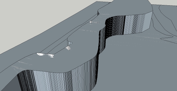
Hey everybody, Im having problems when importing my cad base into sketchup7. I think it could possibly have to do with the survey was created in some other program that civil engineers use alot like land cad. I followed all basic import preparation rules like simplifying, cleaning and purging, and saving as 2004 dwg. The problem is that when I view the lines in SU, they "dance around" and move erratically - not letting me pick endpoints with the line tool and other issues. Some of the cad lines come out correct and behave, allowing for the typical delete short lines/make-faces process that you usually use in an imported dwg. Also, the topo lines look like they were splines or something; I can make faces no problem, but there is alot of "shining" (the white lines and noise that shows on the faces with no explaination) The only explaination is that SU is trying to triangulate way to many faces in too small of an area. I included the model and a jpg of the shining problem. Any help will be greatly appreciated!!!

-
RE: Presentations/sessions at Google 3D Basecamp 2008
Daniel Tal's presentation on organic modeling is a Godsend for Landscape Architects... Ive been figuring out how to do what he's already mastered, Its much quicker to learn from someone else!!!
-
RE: Stamp Tool Woes....
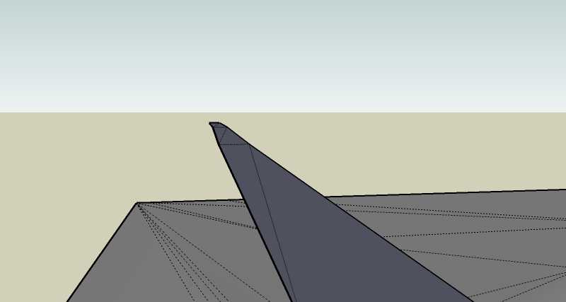
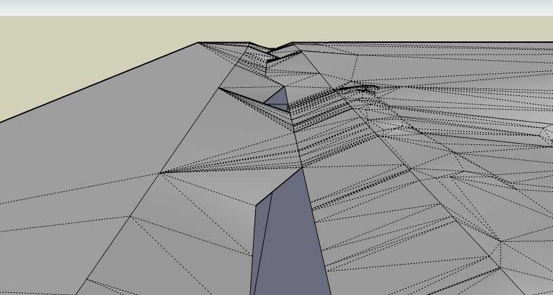
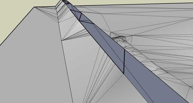
here you go.... the road is broken and rotated a little to match the grade of the road, that is why you see a line dividing it. If you select just the face of the straight part you can see its broken up into little triangles, so I thought mabee this was the problem.... but I tried to stamp just the curved part of the road (it is one coplaner face), and you see what Im talking about....
-
Stamp Tool Woes....
Hey yall, I don't think this is necessarally a newbie question but Ill put it on here anyways... I am trying to use the stamp tool to place a road accurately onto a contour model TIN that I have already created. The problem Im having is that the tool doesn't seem to triangulate the connection between the road and the TIN very well, it criss-crosses the stamp face...aka it doesn't attach the proper side of the stamp face(road), to the correct side of the TIN. Ive tried several offset options but it still won't work. Any ideas whats wrong? It's a HUGE pain in the *SS to go in and erase/add faces to get it looking good, and even if I get it close some of the overlapping edges still shine through and look bad...
-
RE: SU7 Schizophrenic Material Picker
Im having the same problem.... for some reason su 7 just really sucks compared to 6, glitches and splats everywhere. I have to toggle between projected and regular model space just to work on the stupid thing half the time. Mabee has something to do with the free version? I had to reformat my harddrive and I lost all my pro student versions....

-
RE: Animated time + shadows
@unknownuser said:
I just bought the script and it produces a bug splat every time I try to use it... wasted money? If anybody can help it would be great

-
Animated time + shadows
Does any body know how to create an animation of a shadow study, with text (i.e. like text on a leader) of the time that changes with the location of the shadow? You can see it change in the shadow setting box, but I want to make an animation and export it for a presentation. I tried to find a tutorial for this but couldn't. I don't care if it is 3d or 2d text, just a fluid change of the shadow corresponding to the time. Thanks guys for your help so far!
-
Design your own living space with IKEA furniture!
Hey yall, I am trying to put together a new living room of stuff and love the contemporary stuff IKEA carries... I was pleased to find that most of the furniture they carry is already modeled in google warehouse - I just took some quick dimensions of my condo and walla, play around with the furniture I want in a real spatial situation!!! Plus I need an excuse to try out my v-ray download!

-
RE: TIN - From Contours Glitch?
In case anybody has a problem like this, Ive found that skechup (as well as CAD) has problems with arcs that you offset repeated times..... everytime Ive had this problem since I first posted this, I realized it always happens with offset radii.... now I just draw quick free hand contour lines instead of arcs and tangents, the accuracy doesn't matter as long as your close - because triangulation (what SU uses to create a TIN in sandbox) is kinda random and organic, and should be to represent earth forms.
-
RE: Finding breaks or voids
If you could post your model as an attachment it would be easy for one of us to look at it and help you....
-
RE: Advanced follow me tool?
cool, that works pretty good for an extrusion if you want it around a perimeter of a face...
@chris fullmer said:While I don't know of any plugin, and I am no ruby programmer, I still have a couple of hints based on your description of your workflow and the uploaded image.
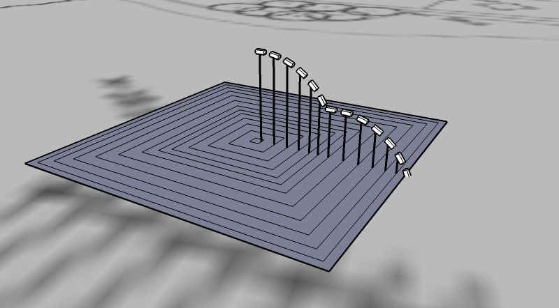
On the groundplane you have an outline for each shape you will run follow me on. You only need one of those squares. I would suggest just having the outermost square. Don't draw all the inside ones. That will save some time. Each face can follow the same square and you'll get the exact same shape.
The second tip, which I think will help, is when you use the follow me tool to go around a simple face, like in your example, there is modifier key that helps immensely. Here's the workflow.
Have nothing selected
Activate the follow me tool
Then click the profile face first
Then hold Alt and click the face that the profile will follow (the groundplane face in your example). By holding alt, follow me will automatcially follow all the edges of that face. I think I made it sound more confusing than it is. Just try it. I've included a test example.Chris
-
Advanced follow me tool?
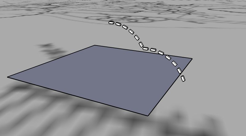
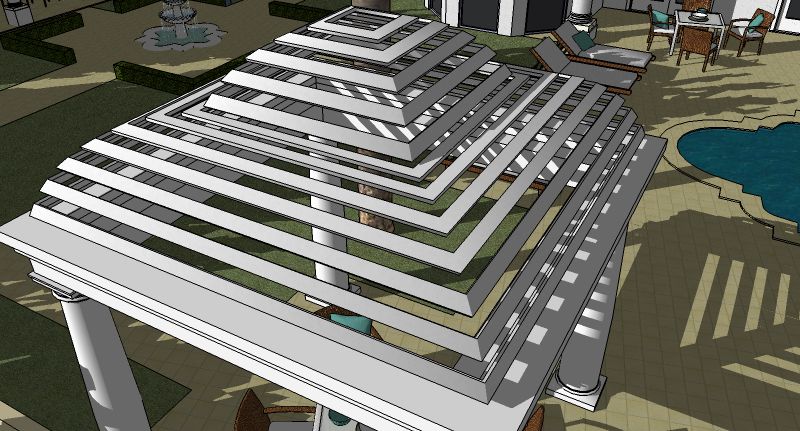
Hey guys, I want to be able to select several faces and extrude them all along a path at the same time. I create things in section all the time and it is a pain to extrude each one separately. For instance, as below, I had to create a separate path for each extrusion on a face below it then select each face I wanted to extrude and select the path I wanted to extrude it on (it worked, but I know theres gotta be a faster way)!!! I tried searching for stuff but couldn't find anything about it.
-
(REQ) random component spray confined inside polyline (face)
I got a challenge for anybody out there who writes scripts. I want a ruby that lets you select a single face and populate it with within the bounding edges with a component. A random placement would be necessary for an organic look. The "random" refers to the placement of the components at the glueing plane, not the scale of the components. For example I would like to create a groundcover bed of shrubs(all identical scale/height) on a single coplaner face. With one click on the face it should populate it with a bunch of shrubs confined by the boundary lines. A density option would be awsome as well. I figure since there is a "component spray" that it should be easy to modify that to be able to
 click once on a face to populate it at desired density. An option for scale randomization would be usefull as well. Right now I just copy groups of plants and re-orient them in an area, then have to go and delete the ones that fall outside the lines (a pain in the azz!) This method can take quite some time to do a good looking bed, the spacing is hard to get right cause when you copy groups and move them a little, they often double-up some individuals which you have to go in and hand pick/delete. I would be forever in debt to anybody that could write this script... if it already exists then kick my asss!