You can setup a layout file linked to multiple SketchUp files. Then when you have updated the files, you can re-render the images from Layout.
You still have to set it up the first time, but then can re-use it as you update your SketchUp files.
You can setup a layout file linked to multiple SketchUp files. Then when you have updated the files, you can re-render the images from Layout.
You still have to set it up the first time, but then can re-use it as you update your SketchUp files.
Often I have various design options for a site, but I want to evaluate them with the same set of scenes, which may change from day to day, or I might add background photos.
My technique is similar to what is described above, but I don't explode my component.
My file with the scenes is called something like "Project master file.skp"
There are a few top level components.
Site Context
Building Design
Landscaping
The Building design component is what I have 4-5 versions of, and I swap out which one I want to view or work on. When I make change to it, I save the component back out before swapping out for another one. I don't rely on it being saved in the master file. This was particularly useful when I had a project with tons of high res photo match scenes. I had to send my design back and forth via email, and this way I only had to send the model element, and not the larger file with the images. In this case my photo match was for the site context, not for the building design.
Scene settings are based on the vertical field of view. Whatever your aspect ratio, the vertical Field of view will be the same. As a result the horizontal field of view is variable.
Interesting. I thought I had the same workflow for all the files, which started with a screenshot from SketchUp. Most of them were done here at work on my PC using Snagit, which saves with an srgb profile. Screenshots at home on mac were made with the OS, and have the "Color LCD Calibrated" profile. I have never had a problem with that profile in the past. Some old MS apps used to not like CMYK jpgs vs. RGB jpgs, but I dont' remember specific profiles being a problem.
Another interesting thing I noticed is that if you keep the "Color LCD Calibrated" profile and save the image to a jpg then and insert that, the PDF export is fine. Save it back to a PNG and you get the error again.
So it seems to be a combination of the "Color LCD Calibrated" profile and the PNG file format. If I get a chance I can try this at home and see if only a windows Layout problem, but I'm flying out of town tomorrow, may not get a chance.
If you have Adobe Illustrator you can open the PDF with it, then if there is a common stroke color or stroke with of the objects that you want to erase, you can use the select options in Illustrator for this.
I can't remember what menu it is under, but it works something like this. You can pick all blue line with stroke width of 0.5.
Not sure if that will help, but maybe? Looks like you want to erase all non-black strokes? If so then select black strokes, lock the objects then select all other strokes and erase them.
If your comfortable working with an XML file you can try this. Of course you can also really mess things up, so work on a copy.
Rename your file.layout to file.zip. When you open the zip files you will see a series of directories and XML files. Back when I used to do this (in ver 1.0) I think things were a little simpler. I see more XML files than I remember, and the code is more complex in some areas. There are a few top level xmls, and then under a "pages" directory" is an xml for every page.
Here is a sample object from a page.
         <e;image id="id1367">
            <e;placedFileReference>
              <e;rectangleBase height="3.531425" width="4.565884" x="1.876357" y="1.966594">
                <e;graphicEntity shouldFill="0" shouldStroke="0"/>
              </e;rectangleBase>
              <e;clipMask>
                <e;rectangle id="id1368" rounding="0" shape="0">
                  <e;rectangleBase height="2.561111" width="2.819996" x="2.801096" y="2.47079">
                    <e;graphicEntity isClipMask="1" shouldFill="0" strokeCapStyle="1" strokeJoinStyle="1" strokeWidth="0.2"/>
                  </e;rectangleBase>
                </e;rectangle>
              </e;clipMask>
            </e;placedFileReference>
            <r;imageFileReference r;id="id1361"/>
          </e;image>
I had even thought at one point of using mail merge or Excel to generate XML flies for Layout pages. In theory you could right a custom application to create a Layout file, or at least the XML to be used in a file. Hmm, maybe a nice SU ruby script.
So you can create new content, but also tons of nice things you could do with a find and replace in the text editor. Do all of you arrows look to big? Find endArrowSize="5" and change it to endArrowSize="3"
I thought I'd try to do a compare of bad png and good png (after you do saveas on it) to see what changed. But unfortunately I can't use an application meant to DIFF text files for this. I'm assuming something in the file header is changing?
For anyone interested. Here is the file (very small png) If I place this in a new Layout file and try to make a pdf, it fails.

I just ran into this problem last night. The PDF failed at all quality levels, but exporting an image was fine. By removing one page at a time, and then specific elements on the problem page, I was able to narrow it down to an imported PNG. Oddly the PNG was fine, but I opened it in an image editor, did a save as, and then inserted it vs. the original file. Everything was fine. I'll see If I can make a clean Layout file and re-create this with the original png. If I can, I'll send it to Google to see what about the PNG causes the problem. The workflow for making this png wasn't different from others in the file.
I haven't looked through this entire post, but I like the idea of picking 10-12 days throughout the year for the simulation, or running the simulation for every day of year but first for 8am, then 9am, 10am, etc. So not as jumpy as going through the year chronologically.
Not quite the same, but I had also setup a LayOut project that had pages for the solstices and equinoxes, at 9am, noon, and 3pm. It had a plan and and elevation view on each page. I was using this to study shading devices,so my my elevation was zoomed in on a window.
As long as I was careful how I named my scenes, I could drop swap out my SketchUp fle in my Layout project, and get a quick shadow studies for any project.
Just wanted to let everyone know we released a minor update to 1.0.5.
We added a few new features:
The tutorials show you how to work with IDF files to add schedules, constructions, new objects such as PV systems, and run batch simulations.
And fixed some minor bugs:
The update is a full downland of the application that will install on top of your old version.
Let me know if you have any questions about the application or problems using it.
New version is 1.0.5.355
--
David Goldwasser
National Renewable Energy Laboratory
Have you tried importing to other applications to see if similar results (AutoCad, Illustrator)
No problem, I just missed it. Looks kind of like bigfoot.
Looks great, I haven't tried this yet, but I'm surprised nobody has posted a beard on Sang or a chi-Sang with grass growing off his head.
If you have the pro version consider using Layout. Then you can add a border, and put multiple views on the same sheet. Then no reason to use another application to do this work. Better workflow when you print many revisions of a presentation.
I think there was another post about this, and I thought about a clunky solution for this. Have you ever taken an architectural model on a base out into the sun to mimic what shadows would be like at a specific time of day/year (ok this is for those of you who built models prior to 3d modeling apps). There was a little sun dial type of thing you put on the base, and that would make sure you had the proper orientation.
So that is an odd kind of SketchUp solution. This would idealy best be done on a copy of your file as it involves moving your geometry.
User experience:
Looks good, I think it will be on my shopping list.
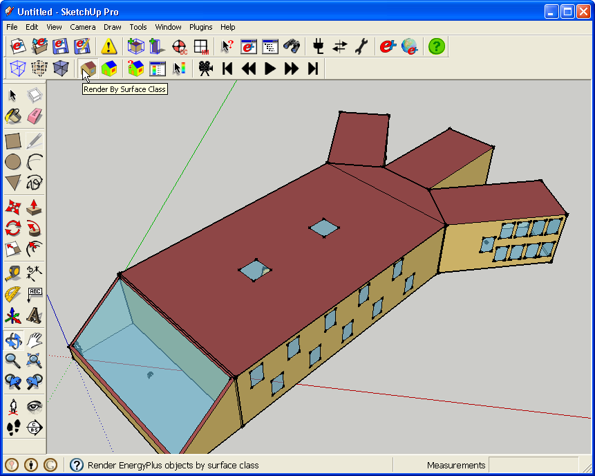
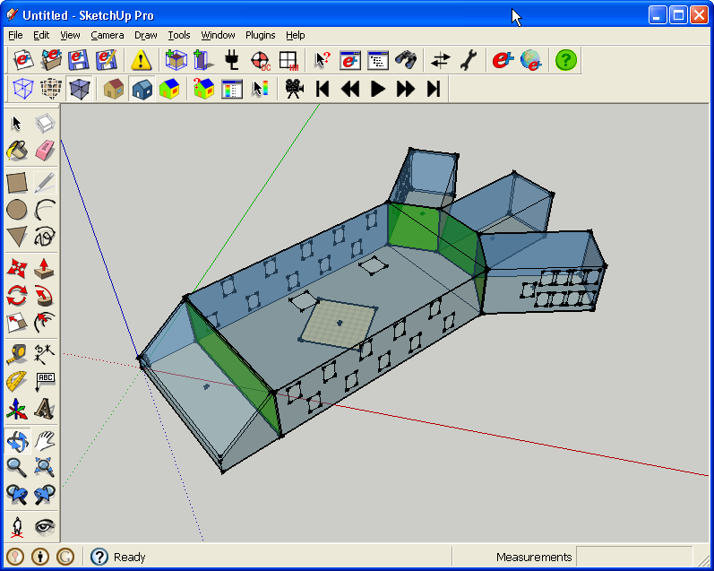
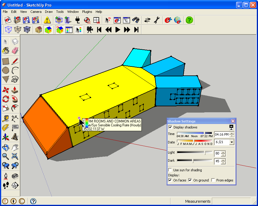
OpenStudio is a SketchUp plugin that allows you to create and edit EnergyPlus IDF (Input Data File) files. EnergyPlus is a whole building energy simulation application. After modeling the building's thermal zones in OpenStudio, the plugin can launch EnergyPlus to run the simulation. Results can be loaded back into OpenStudio for viewing within SketchUp. OpenStudio can also open IDF's created in other applications.
While the previous version focused mainly on creating geometry for the energy model, the new version adds more non-geometry features, outlined below. The installation of OpenStudio includes a reference guide and tutorials on both the old and new features. EnergyPlus also has extensive documentation about its features and some energy modeling tutorials.
New features for 1.0.5:
• Updated for EnergyPlus 5.0.
• Create, view and edit Daylighting:Controls and Output:IlluminanceMap input objects.
• Surface and sub-surface search tool.
• Quickly add internal gains and HVACTemplate:Zone:IdealLoadsAirSystem to zones.
• Automatic surface matching and unmatching tool.
• New render by boundary condition mode.
• Default construction manager.
• Improved documentation and tutorials.
The OpenStudio SketchUp plugin is free and available at
http://apps1.eere.energy.gov/buildings/energyplus/openstudio.cfm
OpenStudio, EnergyPlus, and ResultsViewer all run on Mac and Windows (incl Windows7). EnergyPlus and Results Viewer also run on Linux.
OpenStudio requires Google SketchUp version 7.0 or higher.
You will also need EnergyPlus 5.0 (also free and newly released today)
http://apps1.eere.energy.gov/buildings/energyplus/
Also, ResultsViewer is a new cross-platform tool for viewing output results in EnergyPlus SQLite format and is available at
http://apps1.eere.energy.gov/buildings/energyplus/resultsviewer.cfm
I have attached a few images showing a project in different render modes, but for a better understanding of the software please download the software and look through its documentation. We have a support mailing list at SourceForge, but I'll keep an eye on this thread for questions.
http://openstudio.sourceforge.net/
Thanks,
--
David Goldwasser
National Renewable Energy Laboratory


Or if you do want to use an Adobe app, go for Illustrator instead of Photoshop. You can alter the vector linework, even apply Illustrator strokes to the linework.
Thanks that looks nice. I thought about that at first. I can make a component out of the selection and save out to a file or just keep the component on a layer in the current file.
It doesn't quite work for what I want here, because I want these views to be something the user can edit while they are in. Not necessary change geometry, but we have a lot of attributes, and while they are in their search view want them to be able to select an item to change its name, material, etc. If I have them working in a copy it would be problem to get it back into the model, in particular since the selection isn't just object in a single group, but pieces from all over the model hierarchy.
Advertisement