[Plugin] TIG-Smart_offset
-
TIG (c) 2012-2017
All Rights Reserved.
THIS SOFTWARE IS PROVIDED "AS IS" AND WITHOUT ANY EXPRESS OR IMPLIED
WARRANTIES, INCLUDING, WITHOUT LIMITATION, THE IMPLIED WARRANTIES OF
MERCHANTABILITY AND FITNESS FOR A PARTICULAR PURPOSE.TIG-Smart_offset.rb
Offsets edges of a specified face by a distance 'smartly'
TIG::Smart_offset.new(face, distance)
Overview:
A +ve distance offsets the face's outer_loop outside of the loop.
A -ve distance offsets the face's outer_loop inside the loop.
If the face's outer_loop perimeter contains a thin inlet or thin peninsula
then twisted loops are avoided and trimmed off, only a single non-twisted
new face and edge-set is created.
New edges crossing other coplanar faces will split them as appropriate.
Holes in the face or unconnected but coplanar faces that overlap with the new
geometry might be 'infilled', just as with the native 'offset'.
On completion it returns an array containing the original face and any new
face[s] created or affected by the creation of the new geometry, or 'nil'
if no face could be created - e.g. the face was too small to contain the
internal offset loop using the given -ve distance.
The new face[s] have the same front/back material and layer as the face
itself.
Some very convoluted faces with 're-entrant' forms and 'inlets' can cause
failures, because a fully 'neatened' set of offset edges cannot be determined...Usage:
For developers it can be used as a method to call from within their own scripts.
Add a "require 'TIG-Smart_offset.rb'" line into your code to ensure it's
loading, OR adjust the [modified] code to run only within your own Module/Class.
Remember to distribute this file with your scripts, because users probably won't
have it installed.f = Sketchup.active_model.selection[0] # or other method the define 'f'...
fa = TIG::Smart_offset.new(f, 1.2)'fa' returns as an array of faces - usually one face - created by the operation.
'f' remains as a reference to the original face,
fa[0] etc is the newly created face -
with a +ve distance fa[0] etc is the outer 'donut' ring ['f' is the inner face],
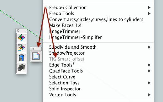
in the case of a -ve distance it is the inner face ['f' is the outer 'donut']OR from the 'Tools' menu > 'TIG.Smart_offset'.
OR from the Context-menu > 'TIG.Smart_offset' .
OR from the [activated] Toolbar > 'TIG.Smart_offset'.Which use the method:
TIG::Smart_offsetter.dialog()In the dialog you enter the required offset in current units,
[or add a units suffix for non-current dimensions].
A +ve offset is applied outside of the face's outer_loop and a -ve offset is
made inside the face's outer_loop.
It mimics the native offset-tool in most respects, other than removing
many of the spurious twisted offset line/loops.
Curves/Arcs are offset as curves in the new offset outline.
ALL selected faces are offset by the distance specified.
The last used offset distance is remembered during that session.
It is one step undo-able for all offsets.
Do not use with the Outliner open and rolled-down, as this may cause splats!Version:
1.0 20121221 First issue.
1.1 20121221 Made more robust.
1.2 20121221 Further robustness in enabling/suitable? [thanks to Jim!].
1.3 20121221 Removed 'suitable?' method, to suit MACs, more error traps etc.
1.4 20121222 Validation on applied to PCs, to avoid MAC toolbar glitch,
1.5 20121224 Coding improved for truer, tidier offsets.
1.6 20121225 Curves/Arcs are now offset as curves in the new offset outline.
1.7 20121227 Further glitches and convoluted offsets trapped.
1.8 20121228 Single welded curve loop offsets correctly. Fixed typo in weld.
1.9 20121230 Error in code when called within another script fixed.
2.0 20121231 Further refinements and glitch trapping.
2.1 20121231 Glitch trapping extended to curves.
3.0 20170510 Made compatible with newer versions...Donations:
By PayPal.com to info @ revitrev.org

-
Merry Xmas to you too.
Nice tool
-
Awesome TIG! Thanks for this one,
Chris
-
Thanks TIG
-
Merry Christmas TIG.


-
Pilou
There is a Ruby Console error message saying it can't be done [clearly it can !]
I knew there was as reason I had never released this code !
Now I need to find out what's wrong with it ??
Merry Solstice... -
Tahnks for the gift before the end of world !

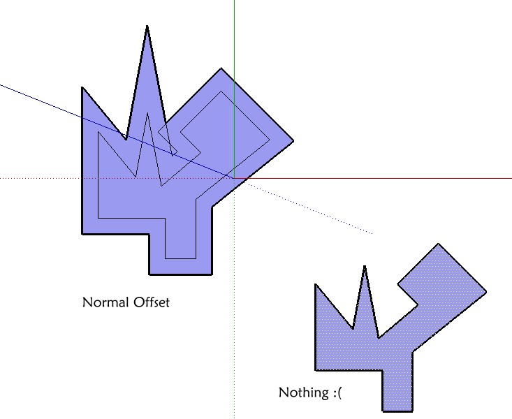
Seems marvellous but...(maybe I miss something

The bow tie must not be disapear ?
(Normal Offset = Native Offset, Nothing = TIG_Smart_Offset )
Sorry for the inconvenience !

-
Bon courage!

-
Works very well. Merry Xmas to you too. Thanks

-
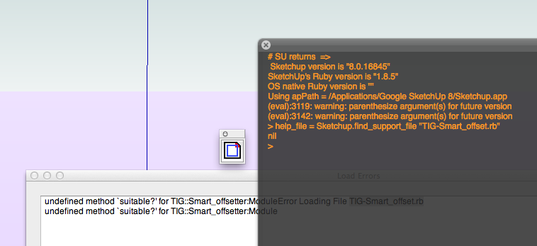
undefined methodsuitable?' for TIG::Smart_offsetter:ModuleError Loading File TIG-Smart_offset.rb
undefined methodsuitable?' for TIG::Smart_offsetter:Module
but worked to a degree, the new border and face are separate and I can't seem to get them to merge with the original face?john
-
@driven said:
undefined methodsuitable?' for TIG::Smart_offsetter:ModuleError Loading File TIG-Smart_offset.rb
undefined methodsuitable?' for TIG::Smart_offsetter:Module
but worked to a degree, the new border and face are separate and I can't seem to get them to merge with the original face?john
Strange there is a method called that ?
It checks selection for suitability and affects how the menu, toolbar and context-menu items display/enabled...
Are you on MAC ?
Was there a line number with that error ?
I'm about to issue v1.1 to resolve Pilou's tolerance issue...
I'll swap some code around to see if making that method earlier fixes it for you...
Let me know whatever you can...
If it's still an issue a sample SKP might help... -
Here's v1.1 http://sketchucation.com/forums/viewtopic.php?p=446462#p446462
It's been made more robust.
It now works on Pilou's problem shapes! -
Hi Tig,
I'll try the new one but something really odd is going on, and yes I'm on a mac.

I used SU to instal, and had line numbers then, so I removed it from 'plugins' to do again, but
this has been uninstalled, moved to trash, emptied trash, restarted computer, but it still there and it works, as well as it did, although sketchup can't find the file.... it's crazy, I don't have hidden files either.I'll over write with the new
john -
found it, a new 'finder. replacement doesn't update instantly... bin that
ok no errors. menu cmd works, context cmd work, toolbar cmd dosen't do anythingIt works if I split if the validation proc
cmd2=UI::Command.new('TIG.Smart_offset'){self.dialog()} cmd2.small_icon=File.join(dir, 'TIG-Smart_offset.png') cmd2.large_icon=File.join(dir, 'TIG-Smart_offset.png') toolbar=UI::Toolbar.new('TIG.Smart_offset') toolbar.add_item(cmd2)john
-
You have no idea how many times I got frustrated doing an offset and have to get in there and clean up the shape. Thanks TIG!
-
i'm all greyed out (on two separate computers with different OS & different versions of sketchup on them).. will investigate more tomorrow

-
Merry Christmas to you too!
-
in
cmd.set_validation_proc(and other places) you want to give the full scope of thesuitable?method since it is being called from SketchUp outside the scope of your module.Also, combine the MF_ bits.
cmd=UI;;Command.new('TIG.Smart_offset'){self.dialog()} if TIG;;Smart_offsetter.suitable?() MF_ENABLED else MF_DISABLED | MF_GRAYED end -
Nice gift! Thank you and Merry Christmas! (Are we allowed to use it before 24.12.?)
-
Yeeeeeeees! Works like a charm now!

You are the Ruby's king!
And lucky because I can't more test your tricky plugin before the next year!


Advertisement


