Mini-challenge
-
@unknownuser said:
@unknownuser said:
At this point SU could be improved with a constuction circle which would not make the program that much heavier. Unlike with true circles.
I really can't think of much reason as to why the devs wouldn't include this in sketchup.. I guess there would be circumstance when new users might not understand why their points placed along a construction circle may not correspond with their circles but I think that confusion happens anyway when learning to deal with segmented circles to begin with.
but other than this possible confusion, can anyone think of a reason as to why the devs haven't included such a feature?
I'm not against true circles. It may just make the program heavier. Not my concern. But how would SU handle surfaces with true circles and true arcs. There would be much more information to deal with than with "just" a few flat faces. True circles would be awesome though.
You may see this happening in the near future, now that the developing team has their hand free. I think that eventually it's a must for a grown up modeling program. -
@wo3dan said:
I'm not against true circles. It may just make the program heavier. Not my concern. But how would SU handle surfaces with true circles and true arcs. There would be much more information to deal with than with "just" a few flat faces. True circles would be awesome though.
You may see this happening in the near future, now that the developing team has their hand free. I think that eventually it's a must for a grown up modeling program.oh, right.. i'm not thinking they should just make true circles for everything.. (basically turning sketchup into a nurbs app).. a lot of people ask for this but by doing so, some unintended behaviors will come into play.. polygon modelers do have some advantages which will be lost in a nurbs based app..
i think i'm wishing for the same thing you are.. just some construction circles so we can snap to any point along an arc when need be..
but at the same time, there may be a reason why the devs have chosen not to include this feature.. i'm sure they've discussed it plenty of times before.. just curious as to what the reasoning may be..
-
I think Tig's Tangent tools should be a native tool in SU, it's the basis of geometry as I learned it.
-
What about a gizmo?
-
IMPORTANT:
My initial version of LibProtractor.rb for the Target trick was full of bugs. I still need some rework to handle all cases properly and anyway I should revisit this protractor tool.In the meantime, please consider the attached version
to drop into the LIBFREDO6_Dir_44 folderFredo
-
Hi fredo
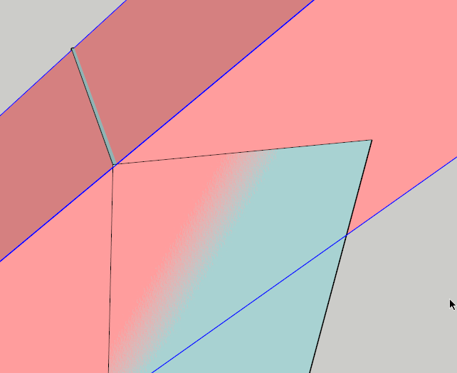
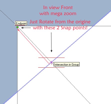
About your previus try with the normal Rotation tool, have you made a very big zoom on the result ? -
@unknownuser said:
Hi fredo
About your previus try with the normal Rotation tool, have you made a very big zoom on the result ?Pilou,
You're right. The rotation is not accurate and we see a small shift when zooming.
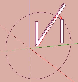
The illusion comes from the fact that, visually from far, we see the edge of the vertical timber.
So it may not be that the standard SU Rotate tool does the job and we may be back to square one

Fredo
-
Damned the trick of jason / Fredo works for me! But....
I had always group that works nut! Never find the "Parallel edges"
But....The secret : explode it!

With group's explosion the rotative block that works like a charm!


Thanks Fredo, my desperation is resolved! Maybe...
 -
Sorry for the desillusion!

I had the same many times during this crazzy Jeff challenge!
-
Tig's method is some tricky but maybe not very simple

Here without plugin and very easy

Seems 1.000000m everywhere
Circle 100 segments (enter 200)
Just 2 rotations
One general

one with big zoom : That all


Edit
Alas with very very very subatomic zoom
seems top blend becomes no accurate
And the second rotate was not theoricly adapted
-
so, after further examining Moujiik's method, i think he has something there
 …i have a way (doing the same underlying thing as Moujiik showed) which might make it easier to communicate..
the thing is, i believe it's still geometrically imperfect but the error must be in the .0000004 (seven decimals) or less range because sketchup keeps reporting it as absolutely perfect (.000000") (in a similar fashion as using math with ruby or a DC can get things perfect within sketchup's maximum precision of six decimals…)
i'll draw up a step by step later tonight so you guys can scrutinize it (and ultimately find the flaw
 )
) -
@unknownuser said:
so, after further examining Moujiik's method, i think he has something there
 …i have a way (doing the same underlying thing as Moujiik showed) which might make it easier to communicate..
the thing is, i believe it's still geometrically imperfect but the error must be in the .0000004 (seven decimals) or less range because sketchup keeps reporting it as absolutely perfect (.000000") (in a similar fashion as using math with ruby or a DC can get things perfect within sketchup's maximum precision of six decimals…)
i'll draw up a step by step later tonight so you guys can scrutinize it (and ultimately find the flaw
 )
)How is this different from gilles? (and I posted a similar one a ways back once I saw gilles method - by drawing a perpendicular to the diagonal). This still has an issue of not aligning precisely to the tangents. You can double-check it easily with TIG's true tangent ruby.
-
it's slightly different with what happens with the angles. maybe enough of a difference to bring things within perfect (well, sketchup perfect) .. I'm getting on the train soon.. I'll post something afterwards.
-
@unknownuser said:
it's slightly different with what happens with the angles. maybe enough of a difference to bring things within perfect (well, sketchup perfect) .. I'm getting on the train soon.. I'll post something afterwards.
Here is the another closed form solution hcos( theta)-ssin(theta) = d
This can reudce to the form of sin(a-theta) = d/m
a= arctan(h/s)
m= is the polar mag of for your orginal post of s=65;h=96
d= lumber width ( 3.5) and if you implement my orginal post suggestion the modeled angle is 54.205( with more accurate guide point interpolation)
The actual angle is 54.178 the other intersect points are d/cos(theta), for the plum cuts) so can be laid out very quickly..IMHO you really don't need SU. Would be very easy to make cut schedule for various s,h and d -
@unknownuser said:
mac1
I was hoping it's already been established in the thread that the challenge isnt about accuracy from a real world construction standpoint. I mean, depending on the time of day (temperature) and humidity, a board will expand/contract far more than the results being given in the thread.We even use to calibrate our theodolites using a long Invar tape before making measurements so I am well aware of temps, ground movement, truck rumble etc etc.
Sorry did not read that I was working off your original post and I thought it implied a actual project working around walls etc.My last post gives the exact answer if you care about that. -
@unknownuser said:
Jason,
You're right.
The native Rotate tool seems to find inference in alignment of edges with others. You have to play around with it, but it seems to find it in the end.[attachment=0:24w854cr]<!-- ia0 -->Jeff Challenge3.gif<!-- ia0 -->[/attachment:24w854cr]
Fredo
I've been mucking around with this too; Fredo I can't replicate your 'parallel to edge'... which edge is it looking for?
-
@andybot said:
How is this different from gilles? (and I posted a similar one a ways back once I saw gilles method - by drawing a perpendicular to the diagonal). This still has an issue of not aligning precisely to the tangents. You can double-check it easily with TIG's true tangent ruby.
ok.. so it's not different.. it's just faster to draw it using a modified version of Moujiik's..
but.. here's something i figured out is different (and it's the reason you were able to get a perfect .000000" measurement in your file (which i missed until now)).. we (you and i at least) are doing something different than others in the thread.. we're working in inches..
.000001" is a lot more of a tolerance than .000001mm
so doing gilles' method in inches -- as long as your board doesn't get too wide, will in fact give perfect sketchup results (meaning smthg like 10.000000") even though it's still not perfect where as working in mm will still show the error..
so this is sort of interesting to say the least.. maybe because i never took the time to realize this:
**.000001 millimeters = .00000003 inches (that's 8 decimals)**so that means, anyone getting this within .000020mm has surpassed the accuracy which is possible with inches in sketchup..
-
Actually, the only reason I was using inches is because it's the native unit for SU. I was thinking I would avoid any possible "rounding to metric" errors. But of course, it all depends on scale, and mm will be a smaller scale giving a higher precision. In the end, checking against true tangent will show the error in any of the cases. (Except now I'm paranoid, maybe true tangent has some built-in approximation as well

 )
) -
@mac1 said:
..IMHO you really don't need SU.
you're right …
[flash=853,480:3ax8n44e]http://www.youtube.com/v/ww17dNJt_LQ?version=3&hl=en_US&rel=0[/flash:3ax8n44e]
… but where's the fun in doing it that way?

[actually, the second method in the video shows something that might make a good ruby.. 2pt orient with 1D scaling]
-
@andybot said:
Actually, the only reason I was using inches is because it's the native unit for SU. I was thinking I would avoid any possible "rounding to metric" errors. But of course, it all depends on scale, and mm will be a smaller scale giving a higher precision. In the end, checking against true tangent will show the error in any of the cases. (Except now I'm paranoid, maybe true tangent has some built-in approximation as well

 )
)yeah.. i'm sure true tangents would eventually show an error.. it just depends on how many zeros you can put after the decimal point..
which is basically what i'm getting at here.. if the people working in mm were limited to 4 decimal places, most of their results (the people using a gilles hybrid) would be showing a perfect measurement across the boardwidth even though we can tell, geometrically, there should be an error..
i think this thread is driving into some weird territory.. we're straddling sketchup's tolerances at amounts so small, it's hard to even imagine.. if this thread keeps going, we'll probably end up pinpointing the exact place where sketchup decides "this is ok.. and this is not ok"
[edit.. or actually, i guess that point is somewhere around 3 one-hundred-millionths of an inch
 ]
]
Advertisement


