Noone?
Oops, your profile's looking a bit empty! To help us tailor your experience, please fill in key details like your SketchUp version, skill level, operating system, and more. Update and save your info on your profile page today!
Check out Febhouse | New extensions for Shadow Analysis in SketchUp Download
T
Offline
Posts
-
Real world revit|archicad <-> sketchup
Curious if anyone has real world experience and success using SU/LO and importing/exporting with other consultants using Revit or Archicad? I'm a structural engineer looking into using SU/LO only. I'm aware that it is certainly possible for me to produce drawings for construction using just this combo, having seen some of the excellent examples here. I also have some ideas for ruby scripts to help.
And I have imported dwg files into SU to help create bases for models, so not concerned there either. I assume that exporting to dwg would be similarly straightforward and fine?
What I'm concerned about is the move to BIM modelling. If an architect or client insists that the project is fully BIM, or at least want to be able to import my model into theirs for coordination/clash detection, would me using SU be a problem for them? This could sway my decision to go with Revit instead of SU.
Thoughts/experiences?
-
Updating references issue
I'm sure I've done something daft. I had a working SU model and LO pages on my MacBook. If I updated the model, saved it, and updated the references in LO, it did indeed update as I had hoped.
I have since moved the files to our office's shared file server. Now if I make a change to the SU model, it doesn't update the references in LO any more.
I did right-click and try "edit in SU" option, and it opened a different file to the one it should be referencing. The filename was a string of numbers and dashes that did contain the original SU model name. I tried to saveas and overwrite the original filename, but still doesn't behave itself.
Is there a way to force which file is referenced? I'm reluctant to have to re-insert the SU model because I've got quite a lot of notes and lines around the details in LO and afraid they'll all go haywire

-
RE: Latest Project - Done and Dusted
That second screenshot is a very realistic render

-
RE: Vignetting or fading a view?
Thanks mate. Had seen that video. Sonder's work is very impressive and inspirational. Been admiring it for a while.
-
RE: Terrain intersecting solids
That's it! Thanks mate. Knew there had to be a simple way.
-
RE: Terrain intersecting solids
Yes. Not so much on the ground, but on the walls for when I elevate them.
-
RE: Terrain intersecting solids
G'day TIG,
I've attached the SKP file. Hopefully it's self-explanatory. In the long section view you can see the gray I'm talking about. The 3D profile of the extg terrain is showing up, while I only want to show the line where this intersects the wall. I could manually trace the line, but wondered if there's a simpler way or command to do it.
Thanks.
-
Terrain intersecting solids
G'day. I've drawn a terrain from contours of existing ground levels and some retaining walls. On a long section of the wall, I'd like to show the original ground levels, but on the elevation some of the shading of the 3D of the terrain is showing as gray. I'd just like to show the line where it meets the wall. Is there a simple way to do this? I played with the colour of the terrain and also it's opacity, but it always seems to display as a gray surface.
-
RE: Basics - creating components and pushpull direction
Thanks TIG. It works the first time I run it, but the second time I get the error:
%(#FF0000)[> sw = StudWall.new
Error: #<TypeError: /Library/Application Support/Google SketchUp 8/SketchUp/Plugins/set.rb:58:in `add_instance': reference to deleted ComponentDefinition>
/Library/Application Support/Google SketchUp 8/SketchUp/Plugins/set.rb:58
/Library/Application Support/Google SketchUp 8/SketchUp/Plugins/set.rb:58:in `initialize'
/Library/Application Support/Google SketchUp 8/SketchUp/Plugins/set.rb:102:in `new'
/Library/Application Support/Google SketchUp 8/SketchUp/Plugins/set.rb:102:in `initialize'
(eval):58:in `new'
(eval):58]class Timber # Timber properties; attr_accessor ;depth, ;width, ;length def initialize(depth, width, length) @depth = depth @width = width @length = length model = Sketchup.active_model ents = model.entities def_list = model.definitions unit_block = def_list.add "unit_block" unless \ unit_block = def_list["unit_block"] unit_block.description = "This is a 1x1x1 block to use as a building block" def_ents = unit_block.entities base = def_ents.add_face [0,0,0], [0,1,0], [1,1,0], [1,0,0] base.reverse! if base.normal.z < 0 base.pushpull 1 inst = ents.add_instance unit_block, [0, 0, 0] ts = Geom;;Transformation.scaling(@length,@width,@depth) block = inst.transform!(ts) end # initialize end # class Timber class StudWall def initialize # input the wall dimensions prompts = [ "Wall Height", "Wall Length", \ "Btm Pl Depth", "Btm Pl Width", \ "Stud Depth", "Stud Width", "Stud Max Spacing", \ "Top Pl Depth", "Top Pl Width" \ ] defaults = [ "2400", "1000", \ "45", "90", \ "90", "45", "600", \ "45", "90" \ ] results = inputbox prompts, defaults, "Stud Wall Properties" # assign the input to variables wH = results[0].to_f.mm; wL = results[1].to_f.mm bPD = results[2].to_f.mm; bPW = results[3].to_f.mm sD = results[4].to_f.mm; sW = results[5].to_f.mm sMxSp = results[6].to_f.mm tPD = results[6].to_f.mm; tPW = results[7].to_f.mm bPL = wL; tPL = wL bPNo = 1; tPNo = 1 sL = wH-(bPNo*bPD)-(tPNo*tPD) # create bottom plate btmPl = Timber.new (bPD,bPW,bPL) # create single stud # pt = Geom;;Point3d.new 0,0,bPD # tr = Geom;;Transformation.new pt # ts = Geom;;Transformation.scaling(pt,sD,sW,sL) # stud = Timber.new (sD,sW,sL) # duplicate studs # insert nogging # create top plate # pt = Geom;;Point3d.new 0,0,bPD+sL # duplicate studs # insert nogging # create top plate # pt = Geom;;Point3d.new 0,0,bPD+sL # tr = Geom;;Transformation.new pt # ts = Geom;;Transformation.scaling(pt,tPW,tPL,tPD) # tP = entities.add_instance unit_cube, tr # tP.transform!(ts) end # initialize end # class StudWall -
RE: Basics - creating components and pushpull direction
Still having some trouble, sorry. I have completely rearranged the way I started out to (try to) make use of classes, modules, methods etc. Seem to have gone backwards.
My intention is to have a 1x1x1 "unit_block" component, then when I want to draw a new piece of timber, do as TIG suggested and transform it accordingly. Timber is going to be a class and it will create the block of appropriately sized timber, then BottomPlate is a subclass of it and will also handle orientations and positions in the wall.
Here's where I'm at:
Class Timber

  # Timber properties;
  attr_accessor ;depth, ;width, ;length

  def initialize(depth, width, length)
    @depth = depth
    @width = width
    @length = length
  end # initialize

  def draw

    model = Sketchup.active_model
    ents = model.entities
    def_list = model.definitions

    unit_block = def_list.add "unit_block"
    unit_block.description = "This is a 1x1x1 block to use as a building block"
    def_ents = unit_block.entities
    base = def_ents.add_face [0,0,0], [0,1,0], [1,1,0], [1,0,0]
    base.reverse! if base.normal.z < 0
    base.pushpull 1

    inst = ents.add_instance unit_block, [0, 0, 0]

    ts = Geom;;Transformation.scaling(@depth,@width,@length)
    timber = inst.transform!(ts)

  end # draw

end # class Timber
I can't for the life of me see where this is wrong. I think I can't see the forest for the trees.
It's giving errors and not drawing an appropriately sized piece of timber when I call
t.new 1, 2, 3or
t.drawSorry for the noob questions.
-
RE: Basics - creating components and pushpull direction
Thanks TIG! That has certainly set me off on the right track. I like the unit cube idea. Have implemented that.
-
RE: Basics - creating components and pushpull direction
Just further to the above, thought I'd try to use selections to make components as you would with the mouse. For a single box (ie the bottom plate) there are 18 entities. I assume this is 12 edges and 6 faces. What's the easiest way to select all of those and make them a component?
And once that is a component and I add more entities (eg the stud), what's the best way to distinguish the new entities from the ones in that first component to make a new one?
Am I barking up the wrong tree here?
-
Basics - creating components and pushpull direction
Very new to Ruby scripting, so please excuse potentially dumb questions.
I'm trying to write a script to draw timber stud walls. At the moment I'm just trying to get the basics working - bottom plate, stud, top plate as components. Later I'll copy the studs at certain spacings along the length of wall, add nogging, allow custom input dimensions etc, and maybe add features for windows/doors etc with jamb studs, lintels and so on.
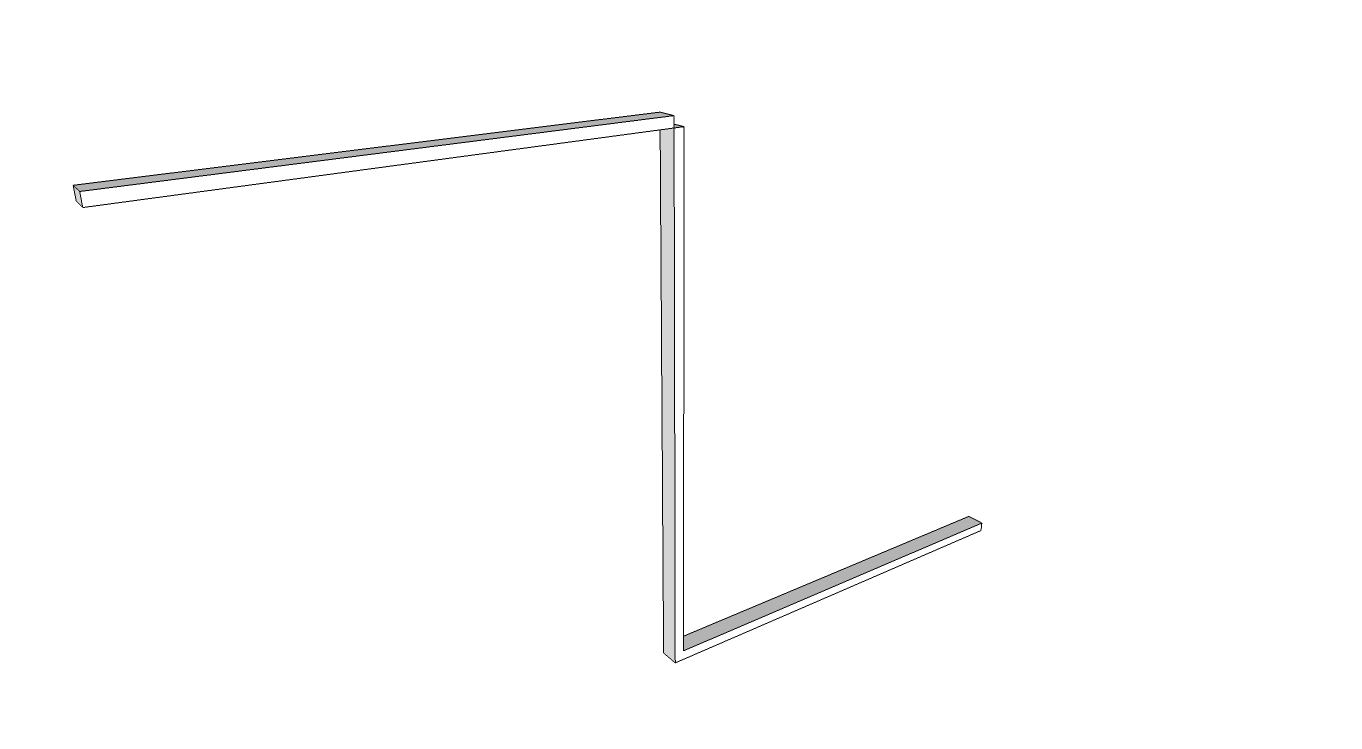
Below is the code where I'm at for now. It works, kind of, in that it draws a bottom plate, a stud, and top plate.
-
But the top plate is being drawn in the wrong/opposite direction to the bottom plate, even though the code is almost identical. See image below. Any ideas why? If I make the bottom plate and stud components as they're created, would that stop this behaviour?
-
That leads to my next stumbling block. I'm at a total loss on how to create a component from each element. I'm reading through the API and "Automatic Sketchup" PDF, but it still eludes me.
-
In future, instead of hard coding the dimensions, I'd obviously like to be able to select an edge or face, click my studwall icon, up pops a window where you can type in the relevant dimensions/properties etc, and it gets drawn as components (dynamic?) that can be edited later if needed. For now, how can I use a selected edge to use for the wall start and finish points?
-
Any other comments/tips/critique you can think of?
## draw a stud wall
# Basics first - bottom plate, studs, top plate
# later look into windows, jamb studs etc

# retrieve the current active model and selection
model = Sketchup.active_model
entities = model.entities
selection = model.selection

# wall overall length and height (outside faces of end studs, bottom of bottom
# plate to top of top plate)
## need to make this use the selection length
wallLength = 2000.mm
wallHeight = 2400.mm

# bottom plates
btmPlLength = wallLength
btmPlDepth = 45.mm
btmPlWidth = 90.mm
btmPlNo = 1

# top plate dimensions
topPlLength = wallLength
topPlDepth = 45.mm
topPlWidth = 90.mm
topPlNo = 1

# stud dimensions
studDepth = 90.mm
studWidth = 45.mm
studLength = wallHeight-(btmPlNo*btmPlDepth)-(topPlNo*topPlDepth)

# stud alignment
studOffset = 0.mm
studSpacingMax = 450.mm

# find the selected edge

# create bottom plate and make a component
btmPlCorners = []
btmPlCorners[0] = [0.mm,0.mm,0.mm]
btmPlCorners[1] = [0.mm,0.mm,btmPlDepth]
btmPlCorners[2] = [btmPlWidth,0.mm,btmPlDepth]
btmPlCorners[3] = [btmPlWidth,0.mm,0.mm]
btmPlSection = entities.add_face btmPlCorners
btmPlSection.pushpull wallLength

# create stud component
studCorners = []
studCorners[0] = [0.mm,0.mm,btmPlDepth*btmPlNo]
studCorners[1] = [0.mm,studWidth,btmPlDepth*btmPlNo]
studCorners[2] = [studDepth,studWidth,btmPlDepth*btmPlNo]
studCorners[3] = [studDepth,0.mm,btmPlDepth*btmPlNo]
studSection = entities.add_face studCorners
studSection.pushpull (wallHeight-btmPlDepth*btmPlNo-topPlDepth*topPlNo)

# copy array of studs

# create top plate face and push
topPlCorners = []
topPlCorners[0] = [0.mm,0.mm,wallHeight-topPlDepth*topPlNo]
topPlCorners[1] = [0.mm,0.mm,wallHeight-topPlDepth*topPlNo+topPlDepth]
topPlCorners[2] = [topPlWidth,0.mm,wallHeight-topPlDepth*topPlNo+topPlDepth]
topPlCorners[3] = [topPlWidth,0.mm,wallHeight-topPlDepth*topPlNo]
topPlSection = entities.add_face topPlCorners
topPlSection.pushpull wallLength
-
-
RE: Why so difficult to install plugins?
You don't need that installer, it just makes it easier.
Just to be clear, what OS are you using and what folder are you placing them in?
-
RE: Why so difficult to install plugins?
Does it show up in the context menu (right clicking I assume). You may have to make an appropriate selection of a group or component first as per http://forums.sketchucation.com/viewtopic.php?t=1702#p7497
The download I see there is a zip file. Did you put the zip file in your plugins folder, or did you extract the rb file into there?
-
RE: Why so difficult to install plugins?
Check out the very simple and useful plugin installer plugin by thomthom: http://forums.sketchucation.com/viewtopic.php?t=42315
-
RE: [Plugin]T2H_BuildingStructureTools2.2.4 in20141207
@sufractal said:
takshata:
I just installed your new plugin, but all of the boxes in the dialog window are filled in 'black' and I cannot see the values inside of them?
Thanks.
Sounds like this problem: http://forums.sketchucation.com/viewtopic.php?f=11&t=45382