Okay, I have 2 models with the Section Cut face in them that are not working correctly. They are both in this folder on Kelly's site:
http://www.sketchucation.com/forums/scf/sas/Ruby/SectionFaceProb
Oops, your profile's looking a bit empty! To help us tailor your experience, please fill in key details like your SketchUp version, skill level, operating system, and more. Update and save your info on your profile page today!
Sketchucation Tools 5.0.7 | Licensing improvements and bug fixes Learn More
S
Offline
Posts
-
RE: [Plugin] SectionCutFace v2.0
-
RE: [Plugin] SectionCutFace v2.0
I'll take a look. It's really big so I'm not quite sure how to do it. I think I can put it on Kelly's ftp.
I tried it with another model that was originally a version 5. With this one it created a face , partally. On of the components that was part of the cut, had a face, and a small enclosed piece of geometry had a face. The rest was empty space. I figured it might have something to do withe the space which was around a component so I exploded everything completely and tried again. The result was the same. The same things had faces and the same things didn't though it was all completely exploeded at this point.
I'll see about getting these models up.
-
RE: [Plugin] SectionCutFace v2.0
Well, yes I have done this. I read all of the notes in the script.
I even exploded all of the parts of the model that were grouped just in case that was the problem. Nothing helps.
Won't create a face. The layer is there, but there is nothing on it.This is an old model but it has been brought into SketchUp 6 and so I can't figure out what the problem could be.
-
RE: [Plugin] SectionCutFace v2.0
I can't make this work. I viewed hidden geometry, I moved the section plane a tad, and I see no surface at all in the section.
I also exported the section and viewed in a free cad viewer and there is no face. What am I doing wrong?
-
RE: [Plugin] SectionCutFace v2.0
I took a look see and I have a couple of problems with the script.
The colours list stops at the bottom of the page ending with the "L" colours and there is no way to scroll down to choose anything else. If I wanted a "White" face colour I could type "W" in the face colour field but then I would have to settle for "Wheat" because that is the first "W" and I can't get at the rest. The Cut face colour actually allows for the "Default" colour but the cut edge colour does not. -
RE: Problem triming
can't tell from just the image. Can you post the skp so we can examine it?
Funny though, it looks like it doesn't have an edge. Did you hide the edge?
Try also selecting the surface and the bounding edges and do an intersect with model.
-
RE: Hourglass on Right Click
Hey Stu. Nice of you to drop in. My hair isn't quite that curly anymore. But most days I look just like that. No hair brush and dressed in PJs and bathrobe. Ah the pleasures of working from home.
-
RE: Hourglass on Right Click
Fine, fine, now let's discuss something really important. Am I not CUTE!! im my picture. Oooh how adorable I am.
-
RE: Push and pull tool
You could also select all the top surfaces that you would have wished to push pull up, use the MOVE tool instead of the push pull and tap the "up" arrow key which will lock all the movement to the z axis direction. MOVe Up 12'. all the attached geometry will follow as it does the push pull tool.
-
RE: [Tutorial > Modeling] How a Pro Builds a House in SU pt 2
Kris, this is probably the most germaine and most required tutorial for SketchUp. So good of you to go to such detail to do this. Great job.
-
RE: Hourglass on Right Click
Gai, there is definitely something funny going on with the signatures.
I did not hit "save' last night instead of submit since it is not even an option in the signature panel, and further I tested it by looking at many of my posst. It was there.
This morning the signature was not. Now look at the top post here. No signature. But this one has it. See, weird? And how weird is it that on the previous post the signature did not show up and then when I went back to it, it did show up.BTW, the problem in this topic IS MOUSE related. Apparently the special mouse puts a NON Microsoft Shell in the registry which is appropriate for it but not for a regular mouse.
I Googled the slow right click thing and it is very commong apparently.
-
Hourglass on Right Click
Just a few weeks ago it started. I have to wait forever for my context menus to show on a right click. My disk is very full (laptop) but it does not need defragmentation, it is quite orderly.
What could be doing it? I did change mice a few weeks ago. I had a special one and it broke so I am just using a standard logitech mouse. both mice are optical. Any ideas?
(inserted afterward as test)
-
RE: Hello Everybody!!!
Where is everybody? Can someone nudge, Gidon?
Any body been in touch with Grant Marshall?Joe Wood, are you here?
-
RE: [Tutorial > Modeling] Square peg in a Round hole
Pleasure! Actually, I should point out that for this particular project the native-to-SketchUp "From Contours" Sandbox tool not only works to create the skin, it works all in one step, faster than the Skin.rb. However, it is good to have both in the arsenal. ( my word was edited!!! It is a word that means weaponry. Go figure. I know what the "editors" were thinking, but this was a legitimate use and only part of a word, Gee.)
The attached is the surfaces as created by the "From Contours" tool.
-
[Tutorial > Modeling] Square peg in a Round hole
This is not exactly a square peg in a round hole, but that was the first good name I thought of. If someone comes up with a better one, please let me know so we can rename it.
I was training an interiour designer and he asked me how to transition a square block into a round base with a concave arced shape joining the square to the circle. This was my solution. I don't doubt there are others.
Thanks so much to Darrel(ArchitectBoy) for his "Skin.rb" script which made the process so very much faster.(PS> Apologies Darrel, I originally misrepresented the author of this amazing script. Please forgive)
![http://www.sketchucation.com/forums/scf/sas/CornerBar/smallsquare_peg_round_hole[2].jpg](http://www.sketchucation.com/forums/scf/sas/CornerBar/smallsquare_peg_round_hole%5b2%5d.jpg)
-
RE: [Tutorial > Modeling] why dont my doors make holes in walls
The fun is in the giving. I'm so glad I could be of use.
-
RE: [Tutorial > Modeling] why dont my doors make holes in walls
I kind of thought so Gai, so that is why I said the "parent"
-
RE: [Tutorial > Modeling] why dont my doors make holes in walls
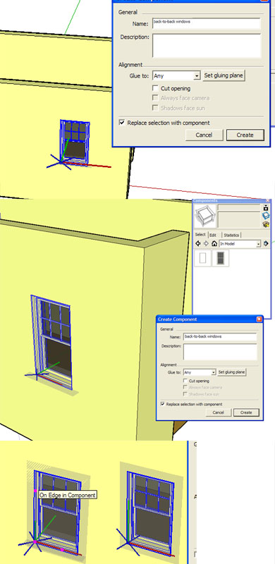
Since this method was first shown in SketchUp V3, there appear to have been some changes made in some of the behaviours. I wanted to put a tutorial together as Eric had suggested and while I was exploring I found a number of oddities, so I had better outline them here.
- The outside window is a SketchUp provided one from the Component Library and the properties are "glue to vertical", Cut faces selected.
- The inside window is a simple component that I made also with "glue to vertical" and cut faces selected.
- I selected both the outside and inside component and made a nested component called "back-to-back windows". I did NOT select cut faces and I did try ALL of the following steps with properties of Glue to Vertical and Glue to Any. There was no difference in the following results regardless of the 2 gluing properties.
-
Regardless of which gluing behaviour you select, SketchUp decides to make the gluing plane the BOTTOM surface of the windows. As long as you do a "Move/Copy from the components existing position, there is no problem. It will copy and it will scoot around corners and place itself correctly on the new surface. The nested components don't cut until you explode the parent. Once exploded they all cut.
-
HOWEVER, because SketchUp has made the bottom surface the gluing plane,they will not come in properly from the component browser. If you look at the icon in the component browser, you will easily see the problem. The icon presents the window with the "bottom" sitting on vertical plane. If you bring it in from the component browser, the windows will be lying down and will attempt to glue to the vertical wall from their bottoms.
-
To avoid this problem, the gluing plane needs to be corrected when creating the component. The pictures in the attached jpg show the progression of steps.
-
The first picture shows the incorrect default gluing plane ( grey surface) and the incorrect positioning of the axis colour segments. The green and the red axis bars define the gluing plane. The blue axis ends up as a little "X" at the origin. So both the green and the red need to sit on the surface that you want to glue to. In the default the green is in the horizotal orientation, not the vertical as it should be.
-
Click on the "set gluing plane" button in the create component window. Your cursor will be attached to the origin point of a new set of axis. I've experimented with this, and it seems to be pretty important to set the origin and the red axis to conform to the real world orientations. Watch out for the "negative" directions, they will mess up the orientation of the components.
Click once to place the origin in the same position that SketchUp selected for the default one, arrange the red axis to be in the same line as the world red axis and click to place it (don't worry about the orientation of any of the other axis it this point, just the red)
Now you can orient your cursor so that the green axis is flush with the surface you want to glue to. Click to commit and then the blue axis will create the little "X" at the origin. Complete the creation of the component. -
Now the component will have the correct orientaion in the component browser, will come into the model and glue in the correct orienation.
But here is a caveat: the move/copy of the original component created will work just fine so long as it is on the same plane. For some reason, it will NOT scoot around the corner properly. You may recall it did the scooting just fine when the component axis and gluing plane were not correct. However, not only will the components brought in from the browser place themselevees correctly on any surface, if you Move/Copy one of them, they will scoot around corners correctly. My guess is that this is a bug of some sort.
Please look at the pictures as your read the steps, it will help in the understanding of the axis directions.
![http://www.sketchucation.com/forums/scf/sas/CornerBar/smallsquare_peg_round_hole[2].jpg](http://www.sketchucation.com/forums/scf/sas/CornerBar/largesquare_peg_round_hole%5b.jpg)