sketchucation logo sketchucation
    • Login
    1. Home
    2. piratebrian
    โ„น๏ธ Licensed Extensions | FredoBatch, ElevationProfile, FredoSketch, LayOps, MatSim and Pic2Shape will require license from Sept 1st More Info
    Offline
    • Profile
    • Following 0
    • Followers 0
    • Topics 8
    • Posts 19
    • Groups 1

    piratebrian

    @piratebrian

    10
    Reputation
    1
    Profile views
    19
    Posts
    0
    Followers
    0
    Following
    Joined
    Last Online

    piratebrian Unfollow Follow
    registered-users

    Latest posts made by piratebrian

    • Automatic finger joint CNC cut path tool

      I just finished a first draft of a Dynamic Component CNC cut layout tool for woodworking finger joints.

      https://3dwarehouse.sketchup.com/model.html?id=ub39eed16-01b5-41c3-afb8-f941ad57737d%26amp;msg=Success!%20Your%20model%20has%20been%20uploaded.%20Please%20note%20that%20it%20can%20take%20a%20minute%20or%20so%20before%20your%20model%20appears%20in%20search%20results%20and/or%20on%20your%20My%203D%20Warehouse%20page.
      It can be found on the 3d warehouse under the name: "Finger Joint dynamic component with cnc cut paths V2 DRAFT"
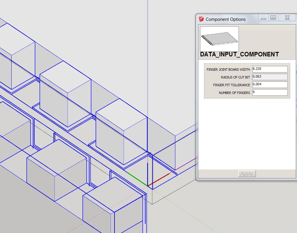
      User inputs are:
      board width
      number of fingers/teeth
      tolerance of fit
      (.002" for hammer tight, .009" fit with glue, or use about .004 for tight fit)
      The spacing is auto calculated using this data.

      As this is a first draft, I don't have the board thickness and finger length co-joined -please just explode and stretch as needed until I can get back to rebuilding the formulas. But the annoying spacing work along one axis is done at least ๐Ÿ˜• Also bit diameter is set at 1/8" I use an Onsrund 2 flute, straight for this kind of work with max pass depth at .070" at 180ipm in finish plywood.
      To use, click into one of the two components until all the joint get blue-boxed, right click and select dynamic component -options. input board width, number of fingers, and tolerance of fit.


      finger joint pic.JPG

      posted in Woodworking
      piratebrianP
      piratebrian
    • RE: The "Duh!" thread (aka the Doh! thread)

      When taking one surface and copy pasting it into an unrelated group, if you click on the destination surface before you do the control-v paste you newly placed surface will auto align. Found this one by accident, it is probably page 2 of the instructions, But bahhh instructions.

      posted in SketchUp Discussions
      piratebrianP
      piratebrian
    • RE: Sketchup To CNC Routering

      I draw a rough rectangle push/puled to its actual material thickness (down to 0.002") then component each part. one copy of the part can sit flat and get auto-updated as you work on the assembled view. Working on the copies of the parts assembled allows you to see every intersection easily. The ones flat on the xy axis are ready for my 3axis cnc for export. Keeping everything in the same file, I hide every other part except the one I need to the cnc via dxf to Thermwood CAM. http://sketchucation.com/forums/viewtopic.php?f=183%26amp;t=51468
      In my guide I wrote I cover just about everything you need to do to bring 2d sketchup dxf to a format that can be easily machined with another CAM program. It explains how to deal with segmented curves, what plugins to use for welding curves, making higher rez text shapes etc.

      posted in Woodworking
      piratebrianP
      piratebrian
    • 3d printed robot parrot

      Here is a robot that I printed using Sketchup.
      Youtube link:
      https://www.youtube.com/watch?feature=player_embedded%26amp;v=NPAw_5zL6-A

      parrotgif.gif

      The parrot was printed on an Afinia 5x5x5" bed mostly out of ABS.
      I traced some profile and front view pictures of parrots. The 3d warehouse had some, but none that I liked. I was attempting to go along the methods used in that great Youtube video: Artisan SketchUp Tutorial: Part 1 I ended up not doing any of that and just started to play with the triangle meshes. Does anyone know what the Plugin is that allows you to grab onto a vertex?
      shape.JPG
      Using the zero thin surface triangular shells I placed downloaded servos from the 3d warehouse, modified to my servo dimensions. I placed the servos inside the shape where I thought it needed pivots and where the essential actuation needs to be to match those goofy goofy birds. For the insides, the 3d printed parts just needed to either hold a servo, or mount onto the servo's arm. So designing parts to jump from servo to the next was fairly easy once the servo positions seemed right.
      arm holder.JPG
      Three plugins that were essential was the .STL export, Fredo's Junction push-pull, and TIG's Smart Offset plugin. After the thin membrane triangulated shape was good and adjusted to fit all the servos even when they move. I used the Junction Push Pull plugin to turn that thin triangulated framework into a thickened shell so there was something of thickness to actually print. In areas where I wanted a triangular open frame look, I used the Tig-smart-offset tool before Junction push-pull tool. That is how I got the open-frame skin look. I had a some lengths of 1/16" brass wire and a selection of both 6-32 screws and 2-56 nuts and bolts to solve problems that glue alone could not fix. To get the 6-32 screws to both act as free moving pivots and tight screw-down connections I printed out a trial and error template with multiple different sized holes to see which one corresponded to a 6-32 screw free fit and a self-threading hole with my preferred printer layer thickness settings.
      test hole.JPG

      The selected diameter circles were then used throughout the assembly via auto component updating. Each of the 15 parts used these components for nearly all the assembly methods. Overall the project took one month of free time including the Sketchup tasks, servo install, and adjusting the Arduiono code for the new body.

      Friends don't let Friends print ABS in enclosed rooms.

      posted in SketchUp for 3D Printing sketchup
      piratebrianP
      piratebrian
    • RE: Sketchup Helix Threads first try garden hose fitting

      I just found a better (?) method of drawing threads by a guy called Andy Sutardy.

      His steps actually used no plugins which was amazing.
      They were:
      make a circle of 24 segments
      explode circle
      lift one segments at random angle.
      delete rest
      copy rotate 23 times, making 24 total one segment of a helix layer,
      copy lift 23 times so the lower one then connects to its neighbor above.
      he then had a segmented helix coil 24 coils all 24 segments.
      exploded, selected one helix, deleted rest.
      scaled it down to be one complete helical revolution, did the measurement to get the lengh per unit thread 1/TPI height.
      drew a cylinder of 24 segements, placed the stacked revolving helix on the cylinder of equal diameter.
      Made one helix be the valley one be the peak,
      scalled peak helix to stretch the thread from the surface of the cylinder.

      Come to think of it. He could then math scaled the helix to get it to scale to a particular dimension after drawing it also. By hiding the hidden surface contours, and selecting one helix or the other, the individual scaling of the outer and inner helix could take place.

      My method lacks as much elegance, but requires less steps. His method is far less cleanup. unhappy with both.

      @cotty said:

      See here: http://www.finewoodworking.com/item/112614/screw-threads-in-sketchup (DaveR)

      posted in SketchUp for 3D Printing
      piratebrianP
      piratebrian
    • Sketchup Helix Threads first try garden hose fitting

      I just finished with (a first draft) of true helix thread garden hose fitting. Does anyone have a better method than what I employed to make the threads?
      The 3d warehouse model is clean for export to a 3d printer, and contains crude step by step text instructions on methods and plugins used:
      picture of threads

      Link Preview Image
      3D Warehouse

      3D Warehouse is a website of searchable, pre-made 3D models that works seamlessly with SketchUp.

      favicon

      (3dwarehouse.sketchup.com)

      It is of the US garden hose with 11.5 threads per inch at 1.044 OD, 0.967 ID inches. I have yet to test it out with abs on my 3d printer. It is not for actual use.
      garden hose thread file
      Thanks also for your wisdom
      PB

      posted in SketchUp for 3D Printing sketchup
      piratebrianP
      piratebrian
    • RE: Plugin for 3D shapes fabrication from plywood

      I am just learning more complex sketchup drawing methods but here is how I made these objects:
      Fredo6 bezierspline(plugin in italics)
      -drew 6 or so f-splines, made some duplicates and scaled/stretched the duplicates.
      -Grouped each line
      Fredo6 bezier tools

      • clicked into the curves one at a time and selected all, bz-convert to, polyline
      • BZ-Convert to, polyline segmentor (select how many segments you want, I used 50 segments for the ones near the ceiling, the more dramatic profiles I used 100)
        Group each profile line.
        Curviloft plugin,
        -it meshed all the curves together.
        DRAPE TOOL or just draw a box, group it, move it so the sides intersect. Explode, triple click (select all lines and surfaces) right click context menu, intersect all.
        clean up edges and delete any excess.
        Slicer (by TIG)
        play with this tool you have lots of awesome options. remember that rgb=xyz for when you choose along which axis you want to slice along.

      For making the file cutable by CNC, grab the curves produced by slicer and use Fredo's Beziersplineplugin to convert those low-rez lines to catmull splines.


      plywood contour v1.JPG


      plywood contour rough v2.JPG


      v8 contour example.skp

      posted in Woodworking
      piratebrianP
      piratebrian
    • Coral pattern question- which plugin would work?

      Hey Awesome people,
      I want to make a coral type structure suitable to my 3d printer. I would like to get some plugin recommendations and or rough procedures. I can draw this,su coral.JPG 
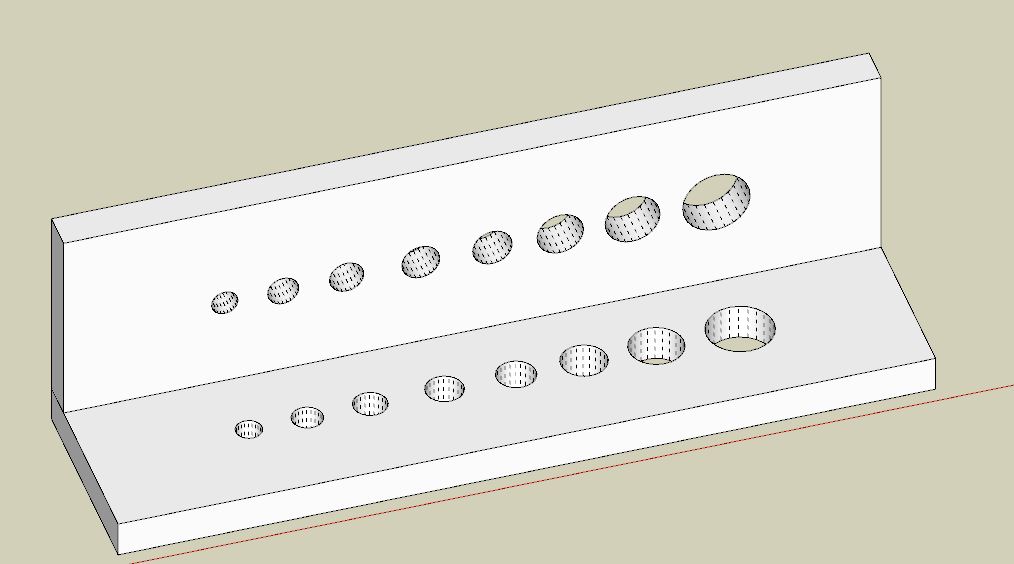
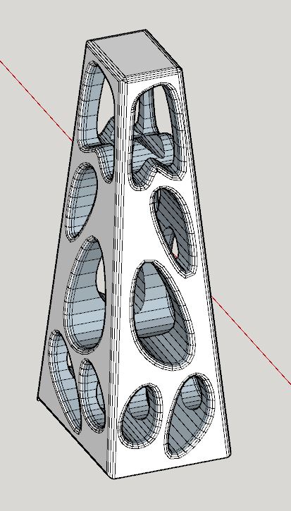
but I would like the radius of the edge to expand to follow the size available to the surface they are placed. Any ideas? I know it is achievable in Rhino, thanks ahead of time! -Brian


      coral.JPG

      posted in Plugins
      piratebrianP
      piratebrian
    • RE: SketchUp to CNC CAM software guide

      Hey jjenks2006
      Sorry I just saw your question. You probably have solved the problem by now. Most of my parts I send to my Thermwood control nesting on the machine have multiple layers extending up into the z axis simply because it allows me to side view all the parts and quick administer the bulk layer naming by window selecting. As bmcintosh mentioned each part has it's outer edge as "outline z0p471" In Sketchup, as long as the camera is on parallel projection and the top view is selected everything exported as a 3d file type dxf out of sketchUp pro comes up as normal cut path individually nestable parts. An outline layer on a 3d dxf part should only be the bottom (or top) face outer edges viewable from top view (blue axis on). I'll have to take a look at that Mosaic Sketchup interface program. You can send a 61.998 by 120.998 dxf to the machine and have it placed on a 62" by 121" table and material so long as the long side of the form is along the x axis and the collar and part clearances are at 0.001. Being able to edit all the part collar and part spacing clearances on the control nesting software on the machine I find easier. This is due to cut problems that can arise on a large job where one warped material/bad drawing can crop up. Being able to quickly identify the bad parts that need re-cut or redrawn and re-nested as additions to the remainder of the 20 sheet job is quite easy with this method. Often on a 10-30 sheet job 3-4 parts need recut/redrawn by the time I reach sheet 7. Que-ing them up for the next sheet is easy so long as 1. you know what you cut (see the printout option on control nesting for a running list of all the parts cut on each material sheet) 2. total of what you want (already listed on the file import of dxf screen). 3. what and how many parts need re-cut. Any re-drawing activity and control nesting them can be done outside of the super controller's activities running the g-code. Going back to cad every time will be tough as it requires a separate inventory scenario.

      posted in Woodworking
      piratebrianP
      piratebrian
    • RE: Not sure why my dc does this axis

      Thanks pcmoor

      posted in Dynamic Components
      piratebrianP
      piratebrian