Thanks bjornkn for your great hint:
@unknownuser said:
Have you tried Plan tools from ThomThom?
viewtopic.php?t=30512
Looks like they could do the job?
Still waiting for the data, though.
Thanks bjornkn for your great hint:
@unknownuser said:
Have you tried Plan tools from ThomThom?
viewtopic.php?t=30512
Looks like they could do the job?
Still waiting for the data, though.
The leading planner at the partner organization kindly sent me some specimens. For the time being the models are all in the AutoCAD DWG format and as WRL-files, which I guess would be VRML?
There are a number of references on Sketchucation about exports to VRML, but couldn't find hints about a way to import WRL-files. The material could be helpful, because at least the colors are correctly defined there. - Any ideas?
Managed to import the AutoCAD material without greater hassle. The colleague pointed out (in Finnish):
@unknownuser said:
The problem with the autocad-file is that the autocad colors are not the same as those aimed at in vrml. In those days autocad didn't have all colors, so our colors were stored as so called xdata in the object for translation /in the VRML file/.
So I've got a bright green roof (wrong color) and nothing else. He promised to check, if he could carry out a conversion to current versions of AutoCAD and 3D Studio which would preserve the colors.
Other problems which I quickly detected:
a) Some of the roofs contain diagonal lines, which obviously could stem from the roof edges not being coplanar. Unfortunately some walls have similar problems (which could become nasty). b) Buildings intersect wrongly. The roofs are built crossing into one another.

Good point, but I wanted to follow the scheme proposed my partners. They don't want to freely share their material with the whole web community. Sales could go down  . Also, I'm not very pleased by all regulations spelled out by some of these 'free' service providers.
My partners informed me that the test data is such a large package that they would have to send it on CD-ROM. We have all necessary server resources needed for the transfer, but thought it would be wise to wait and see. The next challenge is to figure out the format of the data and perhaps to divide it into meaningful chunks.
Thanks for all the clever advice and thanks Alan for the really detailed practical instructions.
I hope to get the material in one day or two. Now I'll be able to tell the wishes that they would be willing to listen to.
Some of the well-meant advice will perhaps not be applicable. I guess they will send a larger environment as a whole, instead of individual buildings. Also, I don't have access to the native programs. Let's see what I can make out of the material.
Ok. I downloaded and installed SketchUp 8 Pro. The Import/Open dialog enumerates the following file types: AutoCAD files (*.dwg, .dxf) and 3DS files (.3ds). No sign of *.obj compatibility, but I'll try out the material with these options.
Hi Anssi, thanks for the kind advice. As you can see from the author's info: I'm a user of the not so professional version, but I've got the right to download the pro version as well. Apparently I need it to carry out the task?
The models are quite old, apparently from 2002 or so. They were actually published for the Cosmo VRML player under the Virtuaalikainuu project. Should I ask for a save in the newest version or does this aspect pose a problem?
Hi. I got an offer from a friendly organization that they would be willing to hand over a number of models which are available in the two abovementioned formats. Although much has been written about such conversions I find it a little hard to sort out the procedures and advantages of each format.
What is the format of choice for importation to SketchUp and what is the standard procedure to follow in order to achieve the conversion. Thanks in advance, ph.
@unknownuser said:
Like actual 3d points or just some sort of spreadsheet?
Thanks Brodie for the interesting material. This seems to be an excellent method for approximating highly complex geometry. Our setting is a bit different. We would like to reduce 'complexity' which is the result of fine measurement errors which should rather be eliminated. The roofs should be rectangles instead of complex geometry.
Although the tolerance of the measurements is rather good (around 0.05 m) the density of the points is only one per square meter. Therefore the end result should be a very abstract representation of the house: roofs and walls.
Photo matching might be useful when we have a chance to study every individual house. Unfortunately this is a wide area located at a distance and we would like to develop a method of detecting houses from the data, then creating rough models as a point of departure for the modeling process. For that stage we also thought of photo matching as a way of adding further detail, although we never used that approach before.
Hi. This should be a FAQ, but I don't find anything helpful by using our search machine.
Let's assume that I have a set of points which would let me deduce the form of a roof for a house and its height from the ground. Is there a readymade plugin which would automate the construction of a rough model of that house?
Thanks in advance. Greetings ph
Thanks Gaieus for your advice.
@gaieus said:
Regarding your window colour: go to your material browser > In model, there select the window colour and go to the Edit tab. At the bottom, there is the transparency slider (I would use a less blue glass however).
I was ignorant enough to try and edit the stock material, which is apparently attributed read only. The controls were at least disabled. [This item should of course have gone into the newbie forum.]
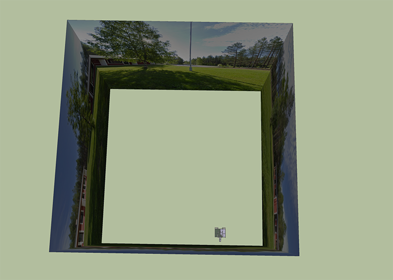
Although a cylinder would apparently produce the best result, the raw material that my kind colleague supplied me was in equirectangular form. So apparently the quick way to the target was not to make a cylinder but a cube. And then we had to place the model into the cube.

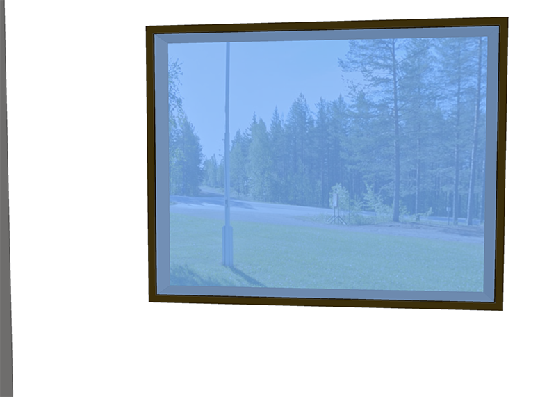
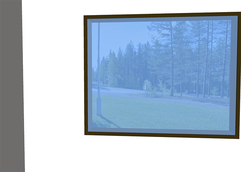
Now to demonstrate what I wanted say I rendered these two images which were separated by just a small amount of panning:


During this panning the background is 'moving' as it should.
One more cosmetic problem: How do I add the level of transparency in the standard Translucent Blue Glass texture?
@unknownuser said:
I am not quite sure if I understand what you mean by thee background moving when the spectator changes viewpoint.
Ok, I'll try to make my point clear by preparing an example. You wrote that you are mapping the panorama background to the surface of a cylinder. Do you have any tools for that?
Yes, I guessed right that somebody must have worked on this.
Checked your interesting gallery and found these two examples:
SU model placed in a panorama picture
http://www.otbdesignworks.com/otb-design-works-vt-callaghan-house.html
This is a good demonstration of a mixed view. Fine work. Congratulations.
View from inside a model with panorama landscape visible through the windows
http://www.otbdesignworks.com/otb-design-works-vt-toni.html
Is this an example of what you described? I don't want to sound impolite but here it seems to me that the panorama landscape is visible in the window, but there is little or no sense of 3D perspectives. It is as if the background was glued on the windows.
Or maybe I just didn't find what you were aiming at. Can you kindly direct me to the correct example where the background would be moving when the spectator changes viewpoint. Thanks, ph
Hi, let me revive an interesting thread. Last weekend we had an exciting demonstration by one of our workgroup members, who is specializing in 360 degree panorama. We made an exercise in panorama photography inside the community house. The colleague also included a nice demonstration with one of our house models placed in a panorama landscape. He used the Cubic Pano Output ruby for that purpose.
While working on the panorama material somebody raised the question whether it would be possible to work out something the other way round:
Has somebody experience from mixing Cubic Pano Output with a background from a 360 degree panorama video? The spectator being 'inside' the living room of the model and watching through the window at the panorama photographed landscape.
@wo3dan said:
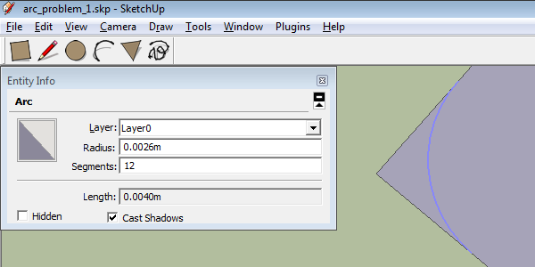
I just made a tangent arc with radius o.2mm by creating a larger one that is "accepted" by SU and then entered the smaller radius in 'Entity Info'. The arc stays tangent but adjusts the radius.
That works. I arrived at the same level of 0.0002 m by using your trick... and that's good enough for our purposes. - Thanks for good advice.
Hi. I experienced some problems in drawing small arcs with the plain SU arc tool. So I thought it would be worthwhile to find out the limits of the tool. Got as low as an arc with a radius of 2.6 mm. Trying to produce something smaller, resulted in corrupted geometry or line segments, but not an arc.
Are there ways of stretching a bit the limits of a regular arc? Hint: Scaling doesn't help.

Thanks guys for the highly interesting material. I'll follow up all these interesting and hopefully helpful hints.
It's nice to see how well this community can respond to various SU-related needs - even in case they are at quite some distance from the main topic.
Yes, please do so. We would anyway of course get the material in digital form, so crossing borders isn't an issue - maybe an asset.
@unknownuser said:
... could still do it for you within your reach.
Sounds reasonable. Is that a guess or do you have experience of such processing?