sketchucation logo sketchucation
    • Login
    1. Home
    2. pcmoor
    3. Posts
    Oops, your profile's looking a bit empty! To help us tailor your experience, please fill in key details like your SketchUp version, skill level, operating system, and more. Update and save your info on your profile page today!
    FredoBend | Powerful new bending tool for SketchUp Download
    P
    Offline
    • Profile
    • Following 0
    • Followers 0
    • Topics 1
    • Posts 378
    • Groups 1

    Posts

    Recent Best Controversial
    • RE: Dynamic components Issue Incorrect dims.?

      you have created some scaling issues within the component...

      Right click the plinth, and see the context menu for scale definition or reset,

      reset the plinth and it returns to its defined size, delete the formula in lenx,lenZ ...it then returns its "current" measure
      It is hard to correct this to some previous version, so it would be best to start again and work within the overall parent size as explained by JQL and so avoid the scaling interaction between child and parent.

      Build the model then apply the size then position formulas such that, after changing a value return it to its original value before the next edit. So if LenX: is 30 cm greyed out, then make the value of the variable or formula equate to 30. then change the variable to see / check the changes then return it back

      sub note: you can use the "scale definition" if it does't effected another part. so a 18mm board could be changed to 16mm, and that scale can be redefined for the component as the original size

      posted in Dynamic Components
      P
      pcmoor
    • RE: Scaling Dynamic Component with nested components

      there is a problem with your version for multiples of 6.5, 13m rounds down to 12, whereas my formula produces the require 3 x 3m and 2 x 2m

      posted in Dynamic Components
      P
      pcmoor
    • RE: Scaling Dynamic Component with nested components

      I believe the common total 3+2+1.5=6.5 should be tried first, then systematically 3,2,1.5

      I used the hidden method to place the sections when not in use, to x=0, and 1.5 length

      What happens to the remainder after the section division?

      attached worked example saved as version 8

      cheers
      Philip

      Edit: 4m is another exemption
      so for range 4 to <4.5 need to take one from the 3m division to allow for two of the 2m division


      TrussLine (1).skp

      posted in Dynamic Components
      P
      pcmoor
    • RE: Dynamic Component help

      Thanks for sharing your model, I have attached a solution

      Some points to keep in mind if you don't already know

      1. Copies shows integer but the formula actually contains a float. So remainder = copies-int(copies) will give the difference

      2. There is a 2.54 bug for metric use, which crops up when using the current or facearea formula. It can appear when trying to use copies, which I found when trying to place formulas at the left.plinth nested level
        So if you get some unexpected result when you are creating DCs using centimeters check it to see if it is a factor of 2.54 (conversion inch to cm) whether multiple or division. For example: Current("lenX")*2.54 will give the correct return for metric. I am hoping this issue will be fixed soon.

      In regards to your model I found it easier to do the workings in the rails component, so I did not have to worry about the 2.54 bug

      the technique: require a whole number and a remainder, can use the int or floor functions to get this

      num= int(length/spacing)
      remain = length - spacing*num
      adjustment = remainder/num

      assuming we increase the spacing until the next full number, then

      copies = num-1
      new_spacing = spacing+adjustment

      1. To make it easier to view your model in Outliner, I suggest you name the components rather than using the default. Outliner is a good tool to select, move, swap ...components as one can easily go to the deepest level and out in two clicks.

      2. Another aspect you could consider is a quantity system, current I use the summary attribute to place specific sizes in metric like "Front Plinth: MDF, Ivory, 150x18, left 45deg mitre, right 45deg mitre, 1205 length". So that I only need to take the summary column of the Generated report for my quantity lists. This report currently uses inches, hopefully it will be fixed with the next release

      3. When it comes to swapping a component and having it update to the current size, which would be the case for doors, one has to reference the LenX,LenY,LenZ to make this happen. I suggest you use aLenX,aLenY,aLenZ as a consistent method so that anyone can swap their style door on the model. So lenX = alenX, then the component will up date to the current lenX when swapped.


      Plinth Box (1).skp

      posted in Dynamic Components
      P
      pcmoor
    • RE: Dynamic Components

      one method is to use the copy function once a certain criteria is obtained
      however as you probably have already discovered making copies of DC holes is difficult. First you divide between front and back cutting planes, then you create a component of the inner raw geometry to build another component inside which we apply the copies formula and spacing distance too.

      Attached is an example

      If you post your model, can modify to suit your needs if this is not what you are after


      holes on rail.skp

      posted in Dynamic Components
      P
      pcmoor
    • RE: Modular shelf components

      cool

      now, I'll have to get that big 3D printer

      posted in Gallery
      P
      pcmoor
    • RE: Dynamic component box

      As previous said, you divide the object into parts and build the relationship between them. A reasonable time consuming effort. So first one must ask whether its worth it. If you going to create say 5 to 10, I would say not...20 to 100 yes.
      Then decide what avenue to take in regards to its use, technically or aesthetically

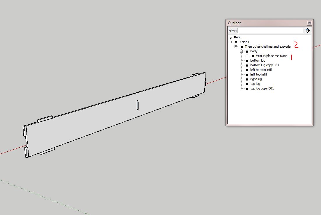
      A method that I currently employ is to create a DC that I can change back to a solid. The DC in the file attached is of one side of the box. Right click it and save it to a designated folder as a component. Now you can change its options to size required, Then by using outliner and expanding the contents you can see two points, one where the hole / slot can be exploded twice, then another where it can be outer-shelled and exploded. These operations can be done by right clicking (context menu) and selecting the appropriate action within Out-Liner. This creates a solid side with just the front wrapper. If you require to change it then swap it for the saved component (it will update to current option selections as it still retains the cover component)

      Capture.JPG
      The benefits of such approach is that one achieves smaller file sizes, protects ones intellectual rights and "Dave can take it off in Cut List"

      The side lugs were done using the normal make a part and build relationship
      the top and bottom done using a copy method

      When I built the slot or hole, I selected a rectangle on the body surface then applied a cut face when making it a component. Next enter the component, push-pull to create sides then delete the front & back surfaces. Exit then created a matching rectangle component with a cutting plane at rear, deleted the surface then moved it into position. Thus creating a movable hole components, these named "front and "back" are the first to be exploded to make a solid body with a hole in when changing the DC to a standard component.

      It took me 3 hours to create this side, so probably a full days work to make a the box...you need always to consider if a DC is worth it (plus half an hour to write and edit this)


      v8 and above

      posted in Dynamic Components
      P
      pcmoor
    • RE: How to Make My Own Custom Dynamic Component

      @simoncbevans said:

      navigating the dialog box for attributes becomes a nightmare.

      The best way to navigate is to use Out-Liner, one click you are into the deepest sub-Component or group. One click on the file name and you are out, or click any other position.(Moreover right clicking a group or component gives menu sensitive options)

      You are always in a clear editing position, however always edit a child's attributes whilst the parent is visible in the attribute dialog, otherwise your geometry is going to lose context and fly around.

      Capture.JPG

      Perhaps the best way is to post a model which you would like to be dynamic and the community can give their ideas on how to build it. Then actual build it in step by step here on the forum.

      posted in Dynamic Components
      P
      pcmoor
    • RE: Dynamic components - help

      Hi

      combined movement with click on arm. however its likely you would want to rotate screen and whole arm, plus other ideas. As the trigger points need to be on one level whereas movement operations can involve combining components for ease of operation it is suggested you create a control pad.

      see attached files


      articulating-arm-8.skp


      articulating-arm with remote-8.skp

      posted in Dynamic Components
      P
      pcmoor
    • RE: Dynamic components - help

      You can use ; semicolon to place multiple events on one onclick line

      onclick may contain animate("RotZ",0,-90) ; set("a". 4,5,8,6) ; animateslow("X" 20,200) and so on. onclick must be triggered at the same nested level, otherwise its parent or container will always precede and stop the lower onclicks

      you can get more than one attribute to be effected by a single onclick event by using a common variable

      steps...........0
      onclick .........aminateslow("steps", 0,100)
      rotz...........=if(steps>50, 90,0)
      X..............=steps/2
      Y............=steps*steps

      examples attached


      the plumb line remains true


      return.skp


      conditional movement.skp

      posted in Dynamic Components
      P
      pcmoor
    • RE: SketchUp 2016 Wishlist

      @pbacot said:

      I would first have to search for that component (if it isn't a group) in a list... bleah.

      From my experience when you select the component or group in the drawing the highlighted entity shows up regardless of its position in the outliner list, clicking once on each expanding button in outliner reveals the nestings, easy to select, copy ,move, explode, outer shell, etc.even multi-select.... then one click completely out. No sore repetitive strain with multi clickings and escapes. Outliner makes it easy, no need to look it up unless you cant actually see it on the drawing, then outliner would show it even if it is hidden

      posted in SketchUp Feature Requests
      P
      pcmoor
    • RE: Quantity of a dynamic component occurrence

      No 😲

      You can only work within the group or component itself. so for a collection, they would be nested within a group component which would determine the copies. This can lead to heavier component or file size, however the contents can all be exploded leaving the parent details, thus a smaller file and when necessary swapped with its definition for further editing.

      Other methods include.....

      You can use outliner and use the filter to show all instances relating to its name

      The report writer will create a list based on a selection or the model

      or use an appropriate plugin or ruby script

      posted in Dynamic Components
      P
      pcmoor
    • RE: Dynamic Component attribute question

      you can use nested if statements, however it is best to use the choose function, based on the dropdown index. CHOOSE(index,value1,value2,...valueN)

      cost =choose(drop,$12,$15.....$n)
      drop item 2 (where the value =2)

      or if value of drop is some function or not a consecutive integer,
      then use OPTIONINDEX("attributeName")
      within the choose function

      cost =choose(optionindex("drop"),$12,$15.....$n)

      the number of choices = numder in dropdown

      posted in Dynamic Components
      P
      pcmoor
    • RE: Measure an arc

      in the entity info box increase the segment to say 100 to make a smoother circle if not already so, right click the perimeter, then choose divide, enter 10
      then you will have 10 arcs that measure 2cm
      (if original circle had 100 segments, then each arch will have 10)

      posted in Newbie Forum
      P
      pcmoor
    • RE: [REQ] Circle by Segment Length?

      I made this DC in response to a question on the SketchUp community about "Generating a 2D irregular polygon for a geodesic floor plan"

      you can easily check the radius for a number of sides for a given length, then match the circle properties to suit


      poly_make.skp

      posted in Plugins
      P
      pcmoor
    • RE: Wall Construction issue

      @jql said:

      Only problem might be subtracting windows as I haven't tested what I'm suggesting

      From my experience using this amazing plugin the surface area and volume takes account of any cuts and voids, however care should be taken when editing if it effects the PMPI length. The PMPI is a hidden line path of the shape, and accounts for the length values on the takeoff.

      posted in Newbie Forum
      P
      pcmoor
    • RE: [Plugin][$] Profile Builder 2

      @whaat said:

      Hi pcmoor,

      Did you create that object with Profile Builder? If so, the length should be based on the length of the underlying path. Using the bounding box to calculate length will not work on a Profile Member composed of multiple segments.

      I created the object using PB2, then used the trim to surface tool, when the surface is within the length of the object, this produced a result where the PMPI is the same length as the short point of the cut. However if i place the cutting surface outside the object the "trim to face tool" extends the object and the PMPI is the same as the long point of the cut.

      so this resolves my issue to create a exact overall cut length. provided I use the extend method

      posted in Plugins
      P
      pcmoor
    • RE: [Plugin][$] Profile Builder 2

      Thanks Dale,

      First, "Whaat" a great plugin!

      However when using the PB Quantifier, the report shows the shorter measure of a cut sheet, is it possible to show the bounding box measure as a alternative or check?

      cut sheet measure.JPG

      posted in Plugins
      P
      pcmoor
    • RE: File sizes

      can you upload an example,

      posted in Newbie Forum
      P
      pcmoor
    • RE: PlusSpec

      @utiler said:

      What I do see however is an opportunity for us as designers to extend our offering to clients in the way of BOQ's given the back end power of PlusSpec. Do yourself a favor and send out a set of plans to a quantity surveyor / estimator and ask for a quote to supply a take off? That's what you will be able to charge after clicking this button. [attachment=0:3vwlrphf]<!-- ia0 -->2015-03-06_0921.png<!-- ia0 -->[/attachment:3vwlrphf]

      What you are saying is incorrect, you can offer a guide, but as far as the structural elements go you would need engineering for the steel, a good understanding of the various codes for timber, etc
      Then other areas would require the professional input like a proper quote for the kitchen cupboards, stairs etc

      The client still needs to go the relevant professions to realise the practicality and cost of his project. Is a professional going to reduce his price just because you got a BIM drawing?

      posted in Extensions & Applications Discussions
      P
      pcmoor
    • 1
    • 2
    • 11
    • 12
    • 13
    • 14
    • 15
    • 18
    • 19
    • 13 / 19