Well..it looks like there's no solution. Ok. Thanks anyway.
Posts
-
RE: How to activate a Section Cut face in a Scene
-
RE: How to activate a Section Cut face in a Scene
@cotty said:
@osage said:
...you can control the Section "active" status in a Scene.. but I can't figure out exactly how to make this happen.
You will find this in the right click context menu.
Ok, here's an update. I managed to get the "cut face" to appear in the required scene, but not the Section cut. But unless I "manually" turn on the Section tool, which then shows a Section in ALL of the scenes, you can't see the cut face. However, turning the Section tool on and off automatically..is exactly what I want it to do, because I want to eventually post an animation to youtube. HOW would a viewer turn the Section on while viewing???
 See..that is my problem. Any insight into this would really be appreciated. Thanks
 -
RE: How to activate a Section Cut face in a Scene
@cotty said:
@osage said:
...you can control the Section "active" status in a Scene.. but I can't figure out exactly how to make this happen.
You will find this in the right click context menu.
Hello again. Thanks for the reply cotty. Sorry it took so long to get back. Had to finish fixing the car in realityland.

Ok, I guessed at what you refered to but my mind reading abilitys are zilch. Assuming you were refering to the "Style dialog box" I opened it, and right clicked on the scene that I want the "section" and "section cut plane" to appear when I click on its tab. A menu came up with various "update" type selections. I tried various combinations of the menu items, but nothing I tried made the section and plane appear in that scene. I STILL have to manually turn the Section tool on for that scene, which would be impossible if I run this as an animation, no?
So, what part of this don't I understand?? Would you mind explaining what it is I am supposed to "right click on' and elaborate what it is I am supposed to select? While this may appear self explanitory to some people, I'm no expert in Sketchup. If I was...I wouldn't be here. But I'm not, so if you wouldn't mind explaining a bit, I'd appreciate it. Thanks -
RE: How to activate a Section Cut face in a Scene
@cotty said:
@osage said:
I've tried setting the "Active Sections Plane" in the Scenes dialog box...
This is the right way. Make the section cut active that should be saved in the scene and add the scene. If you change the active one, you must update the scene to save the new status.
Thanks for replying. I'm still a little confused though. I really don't understand what "active" means? When you say..."If you change the active one..."...that suggests you can control the Section "active" status in a Scene.. but I can't figure out exactly how to make this happen.
Here is what I'm trying to
@cotty said:@osage said:
I've tried setting the "Active Sections Plane" in the Scenes dialog box...
This is the right way. Make the section cut active that should be saved in the scene and add the scene. If you change the active one, you must update the scene to save the new status.
Thanks for replying. I'm still a little confused though. I really don't understand what "active" means? When you say..."If you change the active one..."...that suggests you can control the Section "active" status in a Scene.. but I can't figure out exactly how to make this happen.
Here is what I'm tryindo. Don't laugh.
 I just did this in reality and it worked, but failed to take a video for youtube, so I thought it might be interesting to make a video using a Sketchup "animation" showing what I did, as there are many many DIY auto repair videos on youtube. But no animations.
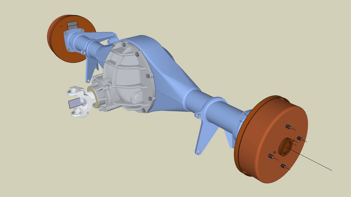
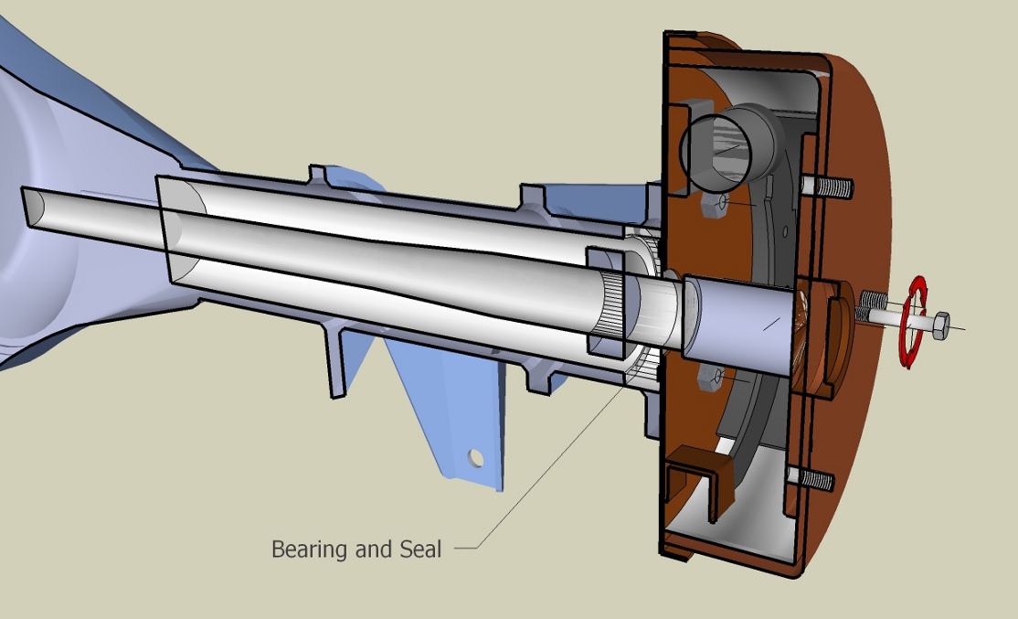
However, this is my first attempt at making an animation, and it's pretty much for my own learning and is of short length. However, the purpose is to illustrate a real DIY technique for repurposing the hub as an improvised tool to pull the axle/bearing composite out of the axle housing by reversing the hub, inserting a couple of long bolts the same size as the lug bolts through the hub, and fastening them to the lugs with a nut. Voila! You now have the equivilent of a $100 "sliding hammer", which most DIY home mechanics do not usually have. And it works great.
Here's the thing though. I have created a model of a typical rear axle on a car, with the hub, backing plate, bearings, brake parts etc. , all on their own layers and groups.
In the first Scene, I want to show an axle only, with wheels removed. I open the Scene dialog box, and select the Location and Visible layers checkboxes only. I create the Scene
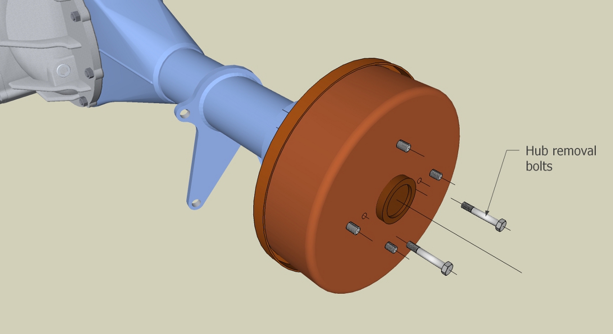
The second Scene moves to a closeup of the right hub. Again, only Location and Visible Layers checked. I create the Scene 2.
The third Scene reorients the view, and I turn on a layer showing two bolts, that are used to force the hub off of the axle hubplate as they often rust together making removal of the hub difficult. They appear. I create Scene 3.
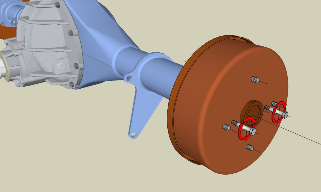
At this point, I want the 4th Scene to show these bolts inserted into the appropiate holes, as I turn off this bolt layer, and turn on a second bolt layer as well as a layer with a "rotational arrow" around the bolt. They appear. I make Scene 4. So far, this works, as I select each Scene tab.
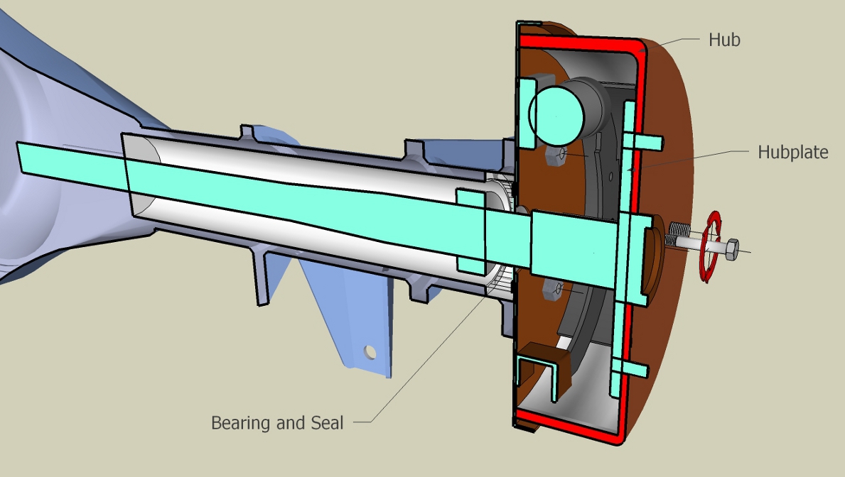
However, this is where things get confusing. For the 5th Scene, I've created a "cut face" on it's own layer, which Sketchup does automatically. I "activate" the Section tool, which I've set up on the centerline of the axle, and activate the Cut Face layer. Indeed, the Section appears, with the Cut face, which then I apply some text. Now I open the Scene dialog box, and check the "Active Section" text box, although I don't fully yet understand what this does.
Anyway, this is where things get weird. I create Scene 5. In the Sketchup model space, nothing changes. However, in the Scene dialog box thumbnail..the Cut Face and text "disappear". WTF? Furthermore, if I move the "select cursor" to the 5th Scene tab, just as it touches it, I don't even click...all of a sudden..I don't do anything...the Cut Face in the Sketchup model space disappears as well!!!
Moreover, if I "remove" Scene 5, the view moves back to Scene 4, but now is in Section view...and now...I have to start all over again on Scene 5!! arrrrrrrrrrgggggggggrrrrrrrrr!!
So...can anyone tell me what I'm doing wrong here?????
That is the problem. So...how do you make a Section with a Cut face appear automatically in a Scene, without having to manually turn the Section Cut tool OFF in previous scenes.
 It seems so intuitive..but it isn't. Thanks for any insight.
Btw, I only show the 1st, 4th Scenes as created. The 5th Scene is only as a jpg of how I want it to look in a Scene, as I can't get the Scene tool to work correctly to actually make a Scene like this. And the last one is what the Scene actually comes out like, as it removes the cut face. And, the section remains in other Scenes. arrrrrrrrrgggggg....

-
How to activate a Section Cut face in a Scene
Hello everyone. It's been ages since I posted a question here and the forums have changed. I really don't know where to put this but here goes.
I've been trying out the Scene tool, and wanted a Section Cut face to appear in a subsequent scene later in the presentation. I investigated various subjects how to use Scene, and have all the layers set up so I can turn them off or on for each scene. I have two seperate Cut Faces on two different layers. I want each of these in a different scene. Unfortunately, when I try to create a Scene showing a Section, I have to activate the Section tool, and then turn on one of the Cut face layers. Then, if I select a previous scene for a test, the Section now shows up in other Scenes. I've tried setting the "Active Sections Plane" in the Scenes dialog box, but it doesn't seem to affect anything. I've tried researching this to no avail.
Furthermore, I don't understand what controls the "cut face" in a scene. Even though it's on it's own layer, turning it on for a specific scene works, but as soon as I try to make another scene, the cut face disappears.
Can anyone tell me how to make a Scene that activates the Section and cut face for that scene only. If I try to play through the scene tabs, I have to manually turn off and on the Section tool for each scene, which seems to contridict how the Scene tool should work. Thanks
-
RE: Group from Slice questions
@unknownuser said:
.hmmm, I didn't know Sketchup would directly export as .dwg/.dxf extensions.
Well dust my britches.. I do now!! I had failed to follow my Dad's main axiom whey you have a problem like this(or most other stuff too). He always said.."You have to LOOK..LOOK ..oh..did I mention...LOOK?"
 Well that's exactly what I did...BINGO! DUH!! When I selected "EXPORT/3D...the file type was default(skp. I think). All of a sudden...it dawned on me... .dwg...DUMB!! There it was. OMG. Ok guys, problem solved. Sorry if you had to read all this crap. Well, at least I found it..and that's what matters. And man am I a happy camper now.
cheers
fitz -
RE: Group from Slice questions
Hello again Dave! Thanks for answering. Yea, I'm importing the "Group Slices"(GS?) into a new skp. as I type.
 But first, I make a component of all the groups I need(3 different axis's), do a "save as" and..VOILA! Too frigin cool! Works absolutely wonderful. This makes my job so easy now I could...well .. Man, Sketchup to the rescue...AGAIN. The more I work with it...the more I love it.
Ok, in regards to exporting..hmmm, I didn't know Sketchup would directly export as .dwg/.dxf extensions. I thought it put them in some other format that "prepares" them for some other program, that you need to do the rest of the conversion. However..if Sketchup WILL do this...OMG..I'd be in 7th heaven.

That's why I was confused about the statements in that link. It sounded like you have to use Sketchup LAYOUT, to do the conversion thing. No matter..I really need to figure this out so I'm going to try everything at my disposal until I get it. (...says the man from the Parallel Universe of "Don't get it")...hahahahaha
Thanks for the suggestion Dave.
fitZ -
RE: Group from Slice questions
OMG...Nevermind..at least about the Group from Slice question. I found the answer. DUH!! I still had the "Section" tool engaged. I guess the Section Plane hides the Group. Well, live and learn. Sorry if you had to read all that.

But I'm still curious how I can re-import these edited groups back into Acad.
Thanks guys.
fitZ -
Group from Slice questions
Hello everyone. I have some problems with the "Group from Slice" option in the Section dialog box.
I have imported a portion of a very large Acad file, which upon importing, becomes a Component. The original Acad file is a very complex 3d of a Recording studio, which when I tried to import, was so large I had to break it down into separate files of different rooms.
I am tasked with producing 2d Acad details from this file, but as it is a 3d file, for me, it is much simpler to see everything in Sketchup. Hence importing it to Sketchup. What I am trying to do, is make various Section planes, and then"Group from Slices" from these sections, and then create a series of Scenes for easy view selections. After I have separated these "groups" I can then zoom in and edit them into details. Which, from what I read here:http://forums.sketchucation.com/viewtopic.php?f=12&t=15911&p=426127&hilit=Group+from+Slice#p426127
,might possibly be re-imported to Acad. But later on that.
However, my first attempt at making one of these Group from Slice seems to either attach itself to the "component" or something, as after I make the Group, I "hid" the component so I could see the group from slice, ...but it wasn't there. I did do some research on this tool, and read that you can move these slices off to the side, which suggests they are a separate entity. No such luck as I can't see them. I tried "editing" the component to see if I could find the Group, but since they are lines along planes...well I've had no luck. I'm sure this is very simple, but I must be missing something.
I did use the "Cut Face" tool too. But this creates something entirely different. I just need the outlines of the object "slice", in group form. Hence my attempt.Second thing is re-importing these edited "groups" back into Acad. In that link above, there was this statement:
@unknownuser said:
Question
Can you export(Group from slice?) layout in dxf/dwg?
Answer
Yes you can and in either model or paper space. What I do for my consultants and my
floor plans is create a group from slice in the section tool. This accurately isolates simply line work of a plan or section. Then export that group only as a dwg file. They then have a simple background without all the crap that they usually have to erase. So far my structural engineers and surveyors have commented on how my drawings are the easiest to deal with. Pretty funny considering I don't even open ACAD to provide them.Well that is a little confusing to me. The question suggests they are talking about Sketchup "Layout", but then the answer suggests : 1. They are talking about Acad, as he mentions Model and Paperspace..or 2. he is referring to Sketchup as he says "create a "group from slice", which to me refers to Sketchup. I'm not that familiar yet with Acad2013, but I haven't seen a "group from slice" in Acad..but who knows?
All I know is I'd "like" to somehow either import or insert these edited "group from slices" files back into Acad. I know this is probably confusing, but if anyone could help me with this I would be so grateful. So far..my workarounds are taking forever...and I'm really running out of time. Thank you for reading my verbose explanation too. Hahaha
-
RE: Need help creating an compoud inside ellipse shape surface
OMG...Living proof there's more than one way to skin an ellipse.

Thanks a million. That's great.
fitZ -
RE: Need help creating an compoud inside ellipse shape surface
@unknownuser said:
Yes, a circle is essentially a polyline. In SketchUp the segments are referred to as "welded."
Hmm, ok. Another thing learned.
@unknownuser said:
You can change the number of segments from the default 24 by getting the Circle tool and typing the new number of segments followed by Enter.
DOH!!
It's been a while since I did that. Well, like they say, use it or loose it...at least when you're my age. Thanks for the reminder. And the reading comprehension heads up too.
@unknownuser said:
The method you used sounds extremely convoluted to me. You probably could have described this process earlier and we'd have figured out what you were doing wrong.
That's odd. I thought I did. Hindsight is 20/20 though. Next time, I'll do exactly that. Regardless..now I have, and now I understand. Sorry. But yea..it was convoluted. Live and learn I always say. But that's why I came here.@unknownuser said:
You should download weld.rb from Smustard.com.
Cool. Will do.@unknownuser said:
So the lesson is to make both curves exploded or both curves welded but not one each way.
Ahhhh...that's what I did. Ok, well that about sums it up.Thanks again for your patience and lessons. It's been a while since I used Sketchup, but I was recently hired as an Autocad detailer and it's so much easier to use Sketchup to see everything first. I'm also in the process of upgrading my Autocad skillsets too, to 3d, using Autocad2013. The last version I used was 2000. Man, like a whole different world.

Which brings me to another question. I've already imported AC files into Sketchup, but haven't found a way to do the opposite. But I'll start a new thread for that one. Thanks again Dave.
fitZ -
RE: Need help creating an compoud inside ellipse shape surface
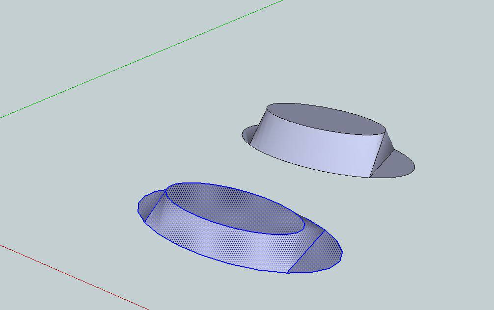
Hi Guys. Ok, I've tried this over 10 times to no avail, using the same ellipse's, from which I originally drew circles, and then DIVIDED them into 100 segments, and then made them into an ellipse, and grouped each one separately, and then exploded as I needed to. These original ellipse parameters were defined by specific dimensions given by the designer as the outer edge of plywood plates. And these then define various parts, which I had to offset from these edges as some were either smaller or larger. After some experimentation, I discovered this process doesn't work on ellipse's that were formed in the sequence I described. Once you divide the circle, and then Scale them into ellipse's..the ellipse boundary, is no longer an entity. It is comprised of individual lines. I don't understand why, but it just doesn't "extrude" or move, correctly. It always has the flat planes at the ends.
Which brings me to a question. Not understanding various SU technical aspects, can you explain something for me. For instance, if I draw a circle, by default(I believe) it is comprised of 12 or 24 segments, I don't remember. But it is a whole entity. That is, unless you explode it. By default, is this entity a POLYLINE?
The reason I ask, since my original ellipses were composed of 100 separate lines, if I make them into a Polyline, the "extrusion" thing still doesn't work. Where as, if I don't divide the circle first, and then Scale them into ellipse's, and then "extrude/move" them, it does work. What I'm trying to find out is, how can you make the ellipse into many more segments, without it getting , well, for the lack of a better term...exploded. If I do not divide the circle first, the divide command(or tool) does not work on an ellipse. Any insight is appreciated.I haven't had time to try the plugin yet. I wanted to solve this puzzle first, as this was something new for me, and I see lots of other uses. Thanks for the patience and the help.
fitZ -
RE: Need help creating an compoud inside ellipse shape surface
@unknownuser said:
Are you selecting just the inside edge and moving it up? Doesn't look like it.
Hello Dave, sorry bout all this. Well, according to the tutorial, you select the "move tool", hover over the inside elipse face, press "ALT", select the face and move it vertically on the Blue axis..which is exactly what I did. Twice. Am I missing something here? I watched the video two times just to make sure. Don't understand it. Nor do I understand what you mean by selecting the "inside edge". They didn't show anything about that. This is what I watched. http://www.youtube.com/watch?v=l2LoHllugqE
fitZ
-
RE: Need help creating an compoud inside ellipse shape surface
Hello again guys. Well, I don't understand what I'm doing wrong with this Autofold tool. I did exactly what the tutorial said, but this is the result I get. Twice. I'm clueless why this is happening, so I could sure use one.
 Thanks
-
RE: Need help creating an compoud inside ellipse shape surface
Ok, just found a youtube tutorial on it. Thanks again.
rick -
RE: Need help creating an compoud inside ellipse shape surface
Man, you guys are FAST!

Geezus...just read the instructions. Ok, that is exactly what I did...except for the "Autofold" part. Never heard of that. I use 8PRO...is that a standard tool? If so...
note to self..file under
"..DOH!"Umm, could you please direct me to it? Thank you.
-
RE: Need help creating an compoud inside ellipse shape surface
@unknownuser said:
So you didn't bother to read my instructions?


 OMG...DOH! I apologize..somehow I missed them. Thank you...mine did NOT work anyway. Just tried it. Ok, I'll pay attention next time. I must have scrolled down too fast. Again...my apology.
note to self..Read EVERTHING..SLOWLY.

-
RE: Need help creating an compoud inside ellipse shape surface
@unknownuser said:
You could also do this quite simply with the native tools.
OMG..I just thought of a way in one move. DUH! Man, hindsight sucks some times. Thanks again.
 -
RE: Need help creating an compoud inside ellipse shape surface
Hey thanks guys.
@unknownuser said:
You could also do this quite simply with the native tools.
Yea, I did it already by hand ..triangles and such..100 endpoints...what a pita. Maybe you know a better/faster way. I'm certainly no SU expert so that's why I came here. To learn. Btw, after I drew this(concept) the overall height dimensions changed because of field dimensions...so whole new curve. Thanks, I'll try the plug. Mucho appreciated Gaieus.
fitZ -
Need help creating an compoud inside ellipse shape surface
Hello. I am looking for a plug in or some method other than by hand, to create a suface similar to the inside of a bowl. I have two ellipses, one large, and a second in parallel planes, one, 16" higher than the lower, both centered on a common axis.
I created the ellipses from a circle, which I hade divided into 100 segments, for smoothing sake. Here is what they look like.


I need this surface to represent a Fabric in a model of a very large ceiling fixture for a Recording Studio. I need this to check for various clearances and to illustrate the final intent for the Fabric installation company. Here is what the unit framing looks like, although it isn't finished by any means.

The two ellipses are actually the two edges where the fabric stretches from and were taken from the actual framework pieces in the model.
Any help would be appreciated as I'm sure there is some kind of plugin to do this. The "Follow me tool" is useless in this context as the curvature changes infinitely as you follow a path. I tried it. So, thanks for any insight.
fitZ
ps. I did search for any information but to no avail.