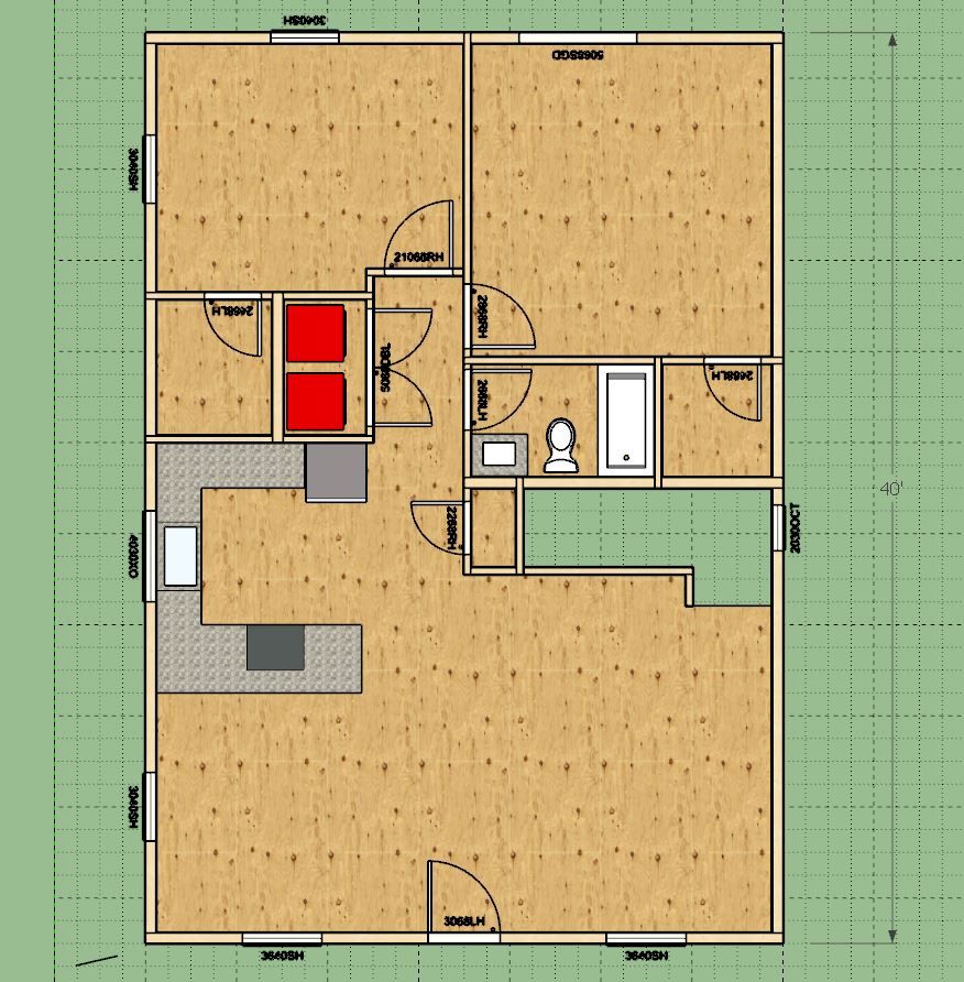
I'm not sure if I want a basement or a second story but this is already bigger than I initially wanted. The water heater (and possibly furnace) will have to live in the basement or second floor (attic). The cut out for the stairs isn't final yet since I don't know what the basement depth might be.
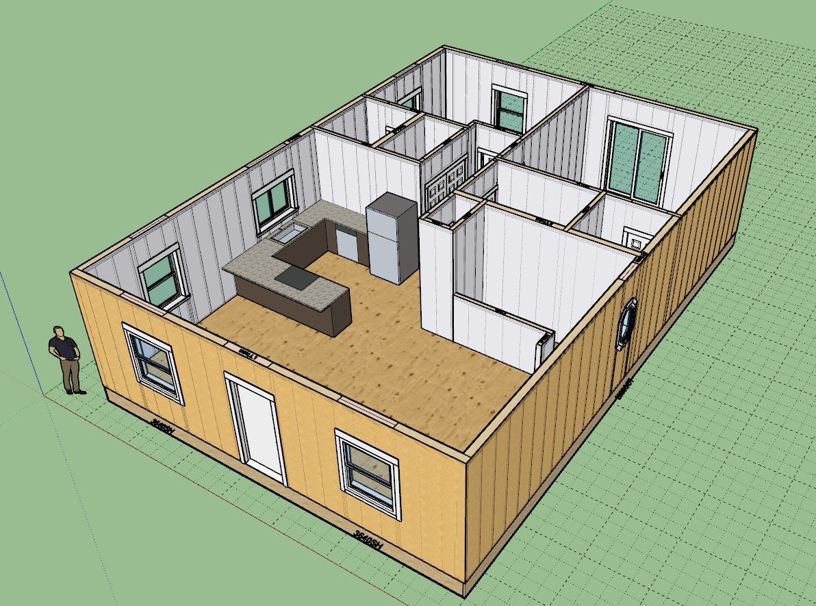
The rectangular outside dimensions is 28'x40', which already puts me at 1,120 sqft for the main level. The bedrooms are quite large, but I prefer larger bedrooms than smaller ones.
Its good for me to use my own plugins once in a while, it helps me find the weak spots or should I say the annoying things about it. One of those things is the placement of doors along a wall when there are other walls that tee into the wall you are trying to place the door into. I need to have some mechanism for snapping or measuring from these other walls. Once can always go back in and adjust or move the doors to fine tune the placement (which is what I had to do) but it does burn too much time. I guess I learn something new everyday.
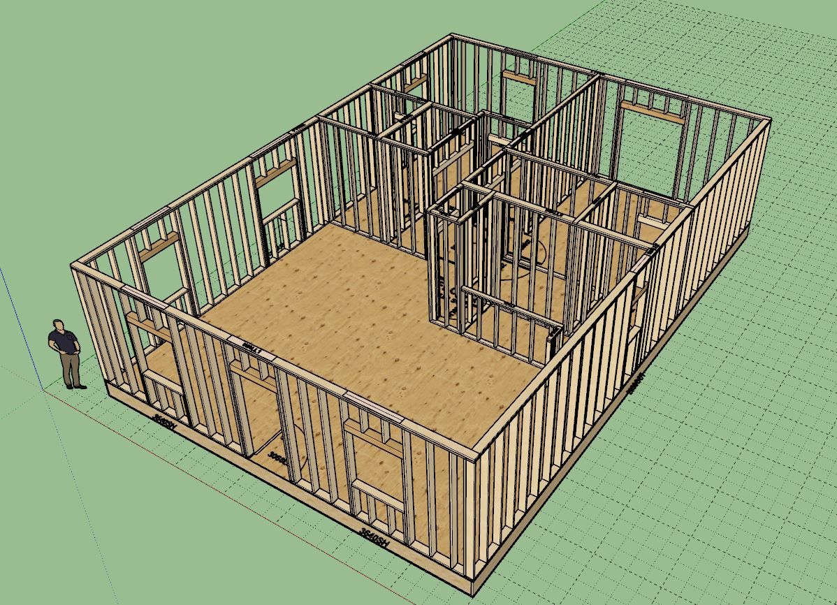
Most of my time was actually spent trying to space plan and figure out what made sense, its kind of like playing Tetris. For this sort of thing a rough layout tool might be useful, but just the native tools at this stage is adequate for most of it. The biggest aid was using the grid to help me find my way. Once my initial layout was more or less final, I popped in the walls in less than two minutes.
Fussing over the windows and doors probably took another hour, and then another hour grabbing fixtures from another model and placing them and then mocking up the kitchen cabinet layout (counters, sink, range, dishwasher and fridge). At this stage I'm not too worried about rendering or making my fixtures all that amazing, so mostly they were added just to make sure my space planning was still logical.
I don't design houses professionally (I've only ever really designed three actual residences and a few detached garages) so if this design is a bit of a cludge please forgive my lack of experience and designer feng shui. Most of my professional work was as an engineer and to be honest that type of work is less about creativity and more about the numbers. I find this type of work far more challenging and invigorating.