Those look very realistic! I like the interior the best too 
Good job!
Those look very realistic! I like the interior the best too 
Good job!
@solo said:
I'm not to familiar with it besides seeing a few renders on this site, I believe it's strength product rendering, how is the texture editor? and lighting controls?
Both are quite good (well...for the renders I want to make). Let's say I can use it with my (low) level of expertise. For me it's just a question of importing the model, editing the textures, maybe adding an HDRI and render!
@solo said:
Which render engine you planning to use?
I think that a built scene would always be nicer, but a good integrated image based scene will also look good.
Currently I am using Bunkspeed Hypershot.
@solo said:
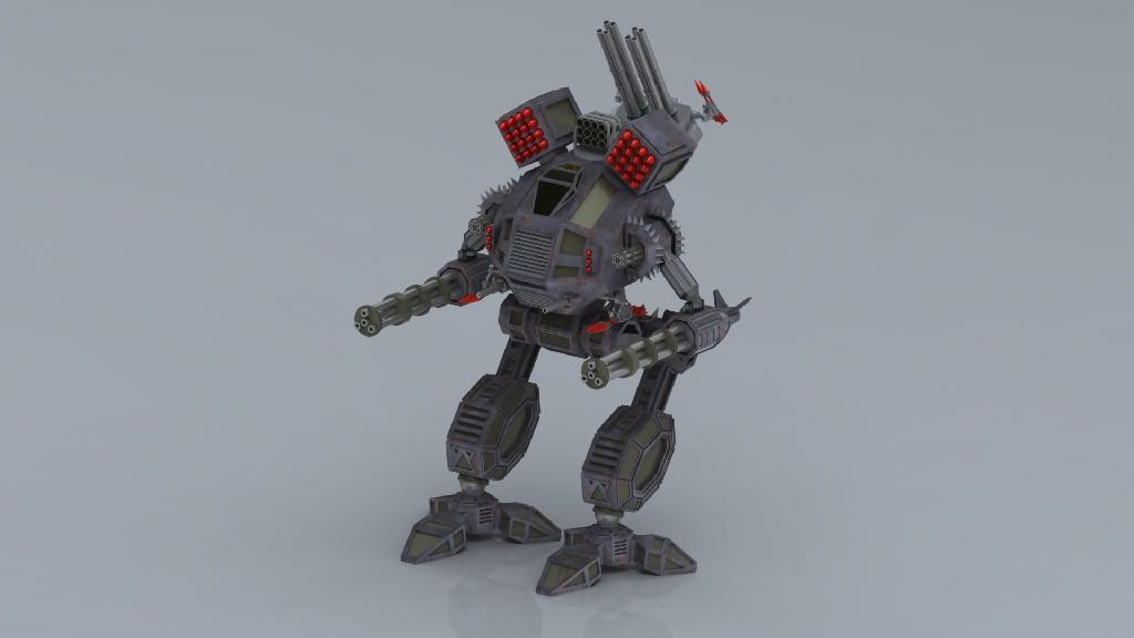
Think he has enough weaponry?
Looking great so far, would look awesome in a demolished city scene with lots of dirty textures and damage.
Any recommendations? Should I use an HDRI or build a scene in SketchUp from scratch?
@xrok1 said:
bigger shoulders.
Thanks for the tip, I'll try to incorporate that into the next update!
@marked001 said:
what's there to say... great modelling and attention to detail! I wish i had this kind of patience.
Cheers 
Problem is, I'm not quite pleased with it yet...so I'm gonna make a few more renders and see what will come of it!
Created with Sketchup 6, rendered in Hypershot 1.7:

Tips/comments/etc. are most welcome!
@mac1 said:
@matsuo said:
Is there a good way to divide the shape after using the 'weld' plug-in? I already tried the following:
- Welding the outline
- Check the length of the outline
- Used 'Convert to > Polyline Divider' and divided it (length of outline / no. of segments (i.e. 20) = segment length)
Problem is that after I did all those steps, a) the shape is distorted, and b) I end up with a gap that is smaller than a segment
What exactly am I doing wrong here? If necessary I will attach a drawing with an example.
MATSUO
Did same approach and did not have the same problem. I found length. inside, is 10652.680 used 101 segs for a tread width of 105.47208mm. The first time checking the segs I found a short one also so, increased the accuracy of the model units to the max. and did not find same problem. Don't know why that should effect the resultsMaybe I did something else wrong). Before copy/ rotation of treads suggest you check each seg length via entity info. The attached file is what I have done to date.
That's more like it 
I will try your approach (increasing the accuracy) and post my results!
Thanks 
edit: Well..I tried your approach, without any success  I keep ending up with one piece that's too small! I even tried the offset on surface tool, but that didn't help either
Any other suggestions?
Is there a good way to divide the shape after using the 'weld' plug-in? I already tried the following:
Problem is that after I did all those steps, a) the shape is distorted, and b) I end up with a gap that is smaller than a segment
What exactly am I doing wrong here? If necessary I will attach a drawing with an example.
@gaieus said:
Dude, first I thought that the image is what you modelled and asked myself "what the hell is this guy doing here in the newbie forum"?
Anyway. If you really want to model it detailed, model one segment, make it a component and copy it along the path of the track (of course, you will need to do a lot of meticulous rotation and such but that should be the only way)
If I only were so good 
So you suggest I should use copy along path (from what I can understand from your post)?
Hi all,
I'm having problems with the following:
I've drawn a (kinda) complex shape of a tank track. I've tried dividing the outline (thus creating the opportunity to place and align any segments), but without any success. I already know how to create simple tracks, but the complex shapes are still a mystery! I've attached both the .skp file and an image to show exactly what I mean. If there's anything that's (somewhat) unclear, please let me know 
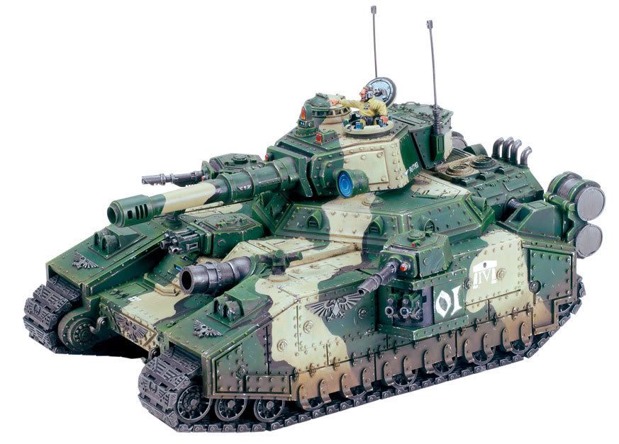
The thing I'm trying to create (specifically the track segments of the tank):

@charly2008 said:
Hi Matsuo,
please have a look at the attached skp-file.
Karlheinz
The image looks great, but I'm unable to open the .skp file, due to still using v6 of SketchUp. Can you repost the file in SU 6 format please? That would be great!
Thanks!
@gaieus said:
Hi Matsuo,
The method would probably be a couple of intersections. But what kind of blade do you want to make? There are so many kinds of swords.
Well, for now I want to stick to a simple blade, let's say a dagger. And from there on I'll try to make more complex shapes if all goes well.
This is one of those things that just doesn't seem to work  . I've tried several methods (like using intersect and scaling) but without any success. Is there a good (and preferable easy) way to make a blade of a sword? Or do I have to get a specific plugin which will basically do it for me?
Thanks in advance!
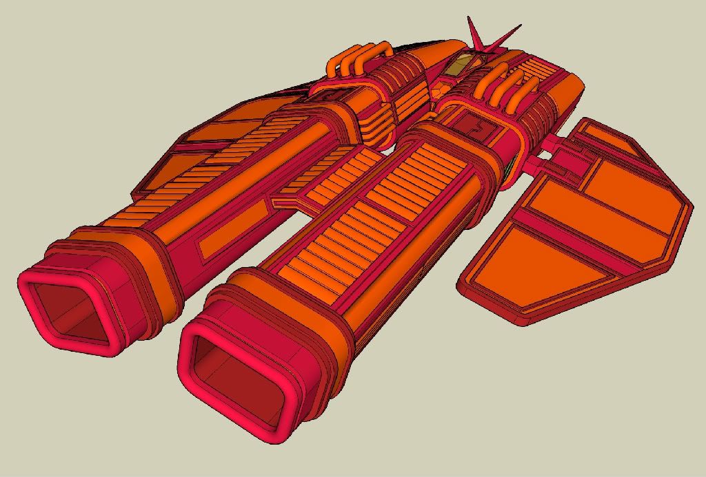
A preview of what I've been working on:

Based on the Wipeout series.
Comments, tips and tricks are most welcome!
@gaieus said:
I don't know, mine starts saving in my custom directory. Are we speaking about the same setting? Window (Sketchup on Mac) > Preferences > Files...
It's the same, and it worked!
Cheers
Just a quickie:
Evertime I want to save one of my projects, I have to navigate to my SU save directory. I know it's possible to set a default directory. The shortcut to SU already has a 'start in' directory, but without succes. Hopefully this is the right place to ask!
Cheers
Not sure if this has been asked before (couldn't find anything):
Every time I use Uniform Scale about Center on an object, I'm forced to keep CTRL pressed (as it should be, right?), but am unable to enter a specific value (say 0.75). Is it possible to use a uniform scale without keeping CTRL pressed?
Cheers
edit: this topic can be closed, I just found the answer in the form of a ruby scaling script 