Ahh! Perfect! Many thanks for that! You’ve saved me hours of searching and trying to figure it out on my own!
I appreciate your reply a lot.
Mark
Ahh! Perfect! Many thanks for that! You’ve saved me hours of searching and trying to figure it out on my own!
I appreciate your reply a lot.
Mark
Hi All:
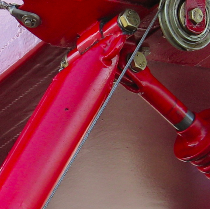
I am modeling a set of steel tube landing gear legs for my Pietenpol Air Camper build. The ends of the landing gear tubes ( 1.375" steel tubing) are squeezed flat on one end, onto which a smaller tube is welded onto this flat edge as a hinge. Like this:

I am trying to figure out the way to take a tube extrusion in Sketchup and pinch it flat on the end at the proper diagonal angle across the tube.
Any advice appreciated!
Mark
Jean Lemire you are a true Gem!
You have solved 2 of my head scratchers yesterday, and today I will be much more productive!! Thanks for the good help!!
Off to make a new wheel!
Mark
@jean lemire said:
Hi Mark, hi folks.
See this SU file for ideas.
Thank you! This was the first time I tried a .5" sphere, so I get why it might have been too small.
I will try as you suggest!
Many thanks!
Mark
I have tried creating a sphere several times and am stumped.
Process:
Draw a 1" circle on the x Plane.
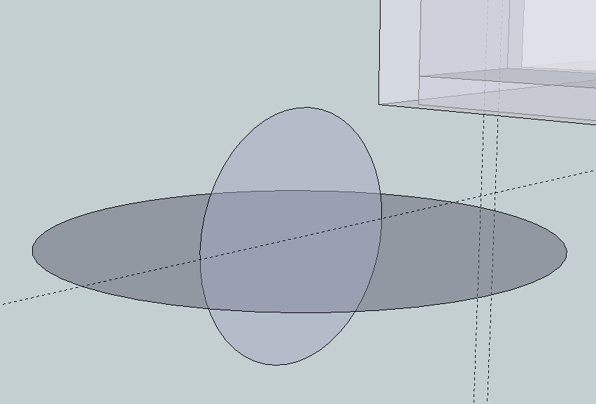
Draw a .5" circle on the z plane, intersecting the centers of both circles, and 90 degrees to each other. Picture 1 below.
Double click on the larger circle to select it with the selection tool
Select the Follow Me Tool.
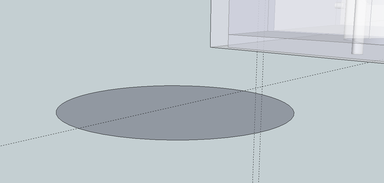
Select the vertical circle face and the vertical circle DISAPPEARS. Picture 2.
I have restarted the program in the event that there is a problem with the program. I have also successfully created a sphere earlier in the day on the same file.
Any thoughts? Help!  )
)
Using the Free version of Sketchup 8.
Mark


Is there a plug in or a way of using the fillet tool to create a fillet around a circle? I have one circle inside another larger circle, where the smaller circle is the hub/bearing of the wheel, and the larger circle is on a lower plane than the inner circle. I want to create a fillet between the 2 circles/layers. how can I do this, as when I select the follow me tool, the warning comes up that it can't be used on curves... see pic below. Thanks!
Mark

I have used a CAD program that allowed math equations in a measurement toolbar to create a quick entity. For example, if I wanted to make a circle with a 27.5mm diameter, I could enter 27.5/2 (27.5 divided by 2) to get the 27.5 mm circle. Sometimes you need to do a calculation like this and I don't know if Sketchup has a way to do this in the program without breaking out a calculator to get the values I need...
Any ideas or plug ins you know of?
Thanks!
Mark
Hey TIG:
Thanks again. You did send me a PM on this. I posted this question about how to cut the tabs off before I PMed you. I posted the question a couple of days before I sent you the PM. I apologize if it appeared that I was badgering ya!
The PM detailed how to do this perfectly. Thanks again!
Mark
Simple Newbie question:
I have drawn some geometry and it is slightly skewed to the plane I drew it in (not sure what I did...)
If I want to force something to a plane, what command do I use and how do I do it?
Thanks!
Mark
OK... this is embarrassing: I've forgotten how to cut the tabs off... Which command will sever them at the cut line..?
Thanks TIG... I'll try that. I thought it might exceed the plug in's capability... Thanks again for the pic/explaination.
Mark
Hi All:
I am trying to use Shape Bender to bend 2 flanges on a metal bracket that joins an engine mount to a wooden fuselage of an airplane.
I have drawn the bracket as shown on the plans (attached). The bracket has 2 'ears' on the top and bottom of the bracket that are bent 90 degrees to wrap around the front end of the fuselage. I want to just bend the 'ear' parts, and not the larger rounded portion of the bracket which is the attachment point for the engine mount. I have removed the holes on the side portion of the bracket that will be used for the attachment to the wooden fuse sides, as I wish to place them after bending.
My concern is that in the bending process with this plug in is that the entire front of the bracket gets bent 90 degrees and not simply the 'ear' portions. Can someone show me how this might work, or is there another script that would do this better?
Thanks so much for the help!
Mark
WOW Jeff! Thanks!
I will do what you suggest. Thanks so much.
I am rather new to this board, and didn't realize this should have been a separate topic, so thanks for the heads up. Next time I'll know. I was thinking all things related to the 'Rails' plug in would be in the same thread, but I see your point and will post accordingly next time.
Again, many thanks. Oh, and that video is worth a thousand words!
Mark
Hey all:
I posted my first attempt at this a couple of days ago, but in modeling the drawer more accurately I have found a problem that I might not be able to work around.
I have tried all I know to do and am stumped. I am modeling a drawer for a friend of mine. We plan to export this as an STL file and use it to make a copy or two of the drawer front to replace ones that were damaged.
I am attaching the most current model I have been working on. To recap the project, the drawer front is contoured on the side and the x and the y axis, and is cupped into the face about .30 inches to create a pocket. The edges of the face is routed in a bit to create a raised face .15 inches high (you can see this on the model on the short sides of the drawer). This lipped edge runs the parameter of the drawer face .375 on the sides, and .25 on the top edge and .5 on the bottom edge.
This lip creates a raised face on the drawer face that is .15 inches high.
Now, on the real drawer, all of this raised portion is cupped in .30 inches all the way across the drawer face. Actually, the raised portion is created AFTER all the cupping is made on the drawer, and THEN the routed edges are made, but I am not sure how to do a pushed face into an already cupped drawer face after applying the Extrude by Rails plug in.
My dilemma: If I add the raised portion of the drawer first (as attached), I can't extrude the sides properly. If I ignore these routed edges, how do I add them after I do the extrude? The face push tool doesn't work on a rounded surface.
The attached drawing might make the above more clear.
I think I am limited by the program, or the lack of another plug in to do this.
I just need someone with all of your experience to tell me to give up so I can know I have stumped the program! 
AH! I found the 'rails' version just after posting, and did the same thing! It worked well.
Thank you so much for your reply, and your PLUGINS!! Many thanks. I eagerly await the update of rails!
Mark
I don't know if this is the right plugin for what I am trying to d, but it looks like what I need. However, I am having trouble making it work. I am trying to help a local wood worker that has a CNC router. They need to create a drawer top that have concave pockets on 3 sections of the face. I am trying to model this in SU and am looking for a plugin that will allow this. Seeing the attached file will make clear what I am trying to describe.
I can't seem to get this plugin to work on this model, but I have gotten it to work on random lines I draw in space to test it. Not sure what I am doing wrong.
The pockets I wish to make on the drawer face are simple curves on the x and y sides. Any help would be appreciated, including suggestions for other plugins that would work for this type of operation.
Thanks!!
Hey xrok1!!
Have you ever had one of those head slappin', ah HA moments where you wished you were smart enough to have seen the obvious??
To quote Home Simpson, Doughhhp!
I think your suggestion will work wonders for me. Eliminating and then re-drawing the little lines is much faster and simpiler than waiting for the 'perfect' plug in 
Thanks for the help!!
Mark
Yes, I have. The weld plugin is what I want to use, but my main problem is actually selecting all of the touching points that make up the line I want to 'weld' together. I am not sure there is a plugin that will be out there, as it is similar to the Select All Connected, and I am not sure how the plugin would know which lines 'connected' you would want to be selected...
Looking at the file I uploaded you can see all of the "sticks" that make up the airfoil. However, the outlines are made of several little lines and I want to convert them into a connected line. Just fishing to see if there is a plugin that I have missed that would select them so I can "weld" them with the weld.rb
Thanks!