1st or 3rd angle projection- what's your preference?
-
I'm asking this question in tutorials, because I'm not sure where to put it, and at the end of the day, this could be useful information for any newbies out there.
The preferred projection angle for engineers in the UK is 3rd angle (and I think it is the same in the USA?), but what is the preferred projection drawing angle for most architects both in the UK and worldwide? 1st angle?
answers on a postcard... (nope only joking!)
Answers here please!
Tom
-
I have never heard or used the phrase 3rd Angle Projection. That may be jargon unique to the UK. Is this in reference to 30,45,60,90 degrees for isometric projection?
-
-
@mitcorb said:
I have never heard or used the phrase 3rd Angle Projection. That may be jargon unique to the UK. Is this in reference to 30,45,60,90 degrees for isometric projection?
That's interesting. Is your background in architecture? Mine was a degree in engineering, but I wish I had studied architecture.
3rd angle projection is definitely an international term. We were lead to believe that it was 1st angle that was used in the States, and 3rd in the UK/ Europe, but I found that out to be not the case.
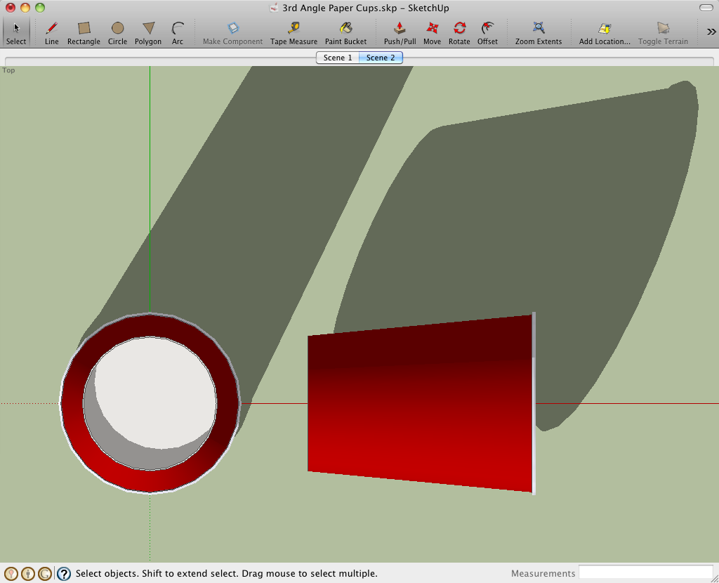
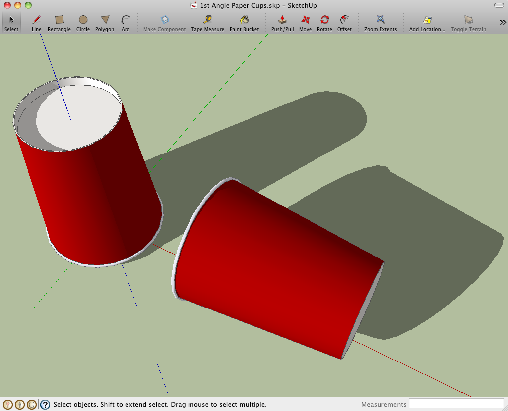
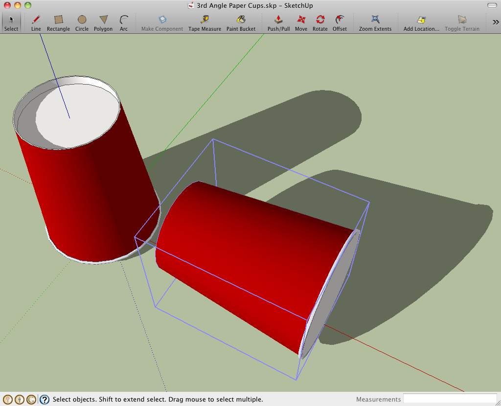
I'm writing a book (for kids) and I want one or two pages on orthographic projection in there. At the moment I've used a paper coffee cup to demonstrate how the projection symbol dedmin has provided a link to works. (In SketchUp of course!)
mitcorb (or anyone else for that matter!), if you draw a 3D plan, how do you draw the projection? In 1st or 3rd angle?
Tom
-
The closest term I would guess is 1 point or 2 point perspective? Maybe it's 3 point...been too long since I have picked up a pencil and had to set out vanishing points.
-
But would you have laid out a 2D drawing with a front, side and plan view?
I've seen many an architects drawing where at the bottom is the front view, above that is a top view and on the right side a side view. Do draughtsmen (people) not do that anymore? Have we been spoilt by SketchUp or do draughtsmen still use AutoCAD?
-
Okay - so this is what you are talking about.
http://www6.district125.k12.il.us/teched/Courses/TDresources/3rd%20%26%201st%20Angle%20Proj.htmlI started off my Architectural career with a degree in drafting - we had to do those type of drawings for machine and tool making, but don't do much isometric drawings for architectural work anymore....if at all.
I thought you were talking about building a perspective like the following.
http://www.tpub.com/content/draftsman/14276/css/14276_277.htmI think some folks, for small projects, might still have a plan with a front and side elevation similar to what you are speaking of. I try not to use elevations with clients, they aren't always trained to know how to read them - that is what I use sketchup models for now.
I still use cad...to do some work prior to bringing into sketchup - but over the years it has become easier for me to start in sketchup as well. -
There is this Wiki article:
http://en.wikipedia.org/wiki/Engineering_drawing
which is inaccurate regarding UK standards, which is third angle (also see the discussion http://en.wikipedia.org/wiki/Talk:Engineering_drawing).
There is also this article:
http://en.wikipedia.org/wiki/Architectural_drawing
Regards,
Bob -
... extract...
First-angle projection [FR/EU] is as if the object were sitting on the paper and, from the "face" (front) view, it is rolled to the right to show the left side or rolled up to show its bottom. It is standard throughout Europe (excluding the UK) and Asia.
First-angle projection used to be common in the UK, and may still be seen on historical design drawings, but has now fallen into disuse in favor of third-angle projection [US].
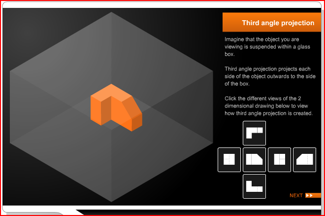
Third-angle projection [US] is as if the object were a box to be unfolded. If we unfold the box so that the front view is in the center of the two arms, then the top view is above it, the bottom view is below it, the left view is to the left, and the right view is to the right.
It is standard in the United Kingdom (BS 8888:2006 specifies it as the default projection system), USA (ASME Y14.3-2003 specifies it as the default projection system), and also in Canada, and Australia etc.
In 'first-angle projection' [FR/EU], the "top" view is pushed down to the floor, and the "front" view is pushed back to the rear wall; the intersection line between these two planes is therefore closest to the large end of the cone, hence the first-angle symbol shows the cone with its large end open toward the donut.
In 'third-angle projection' [US - and all sensible nations], the "top" view is pulled up to the ceiling, and the "front" view is pulled forward to the front wall; the intersection line between the two planes is thus closest to the small end of the cone, hence the third-angle symbol shows the cone with its large end away from the donut.
??? -
Hi, tfdesign:
I hope this doesn't come off too abrupt or rude, because I surely do not mean it:
I have been a licensed architect since 1989. I have not encountered the terminology in the subsequent years. In my years of education, technical drafting was never presented as a requirement. We were expected to just pick it up and learn it by doing. When I was in middle school, approximately 13 years old, I took an elective class dealing with intro to woodworking and drafting. Even then, the 3rd angle projection was never mentioned. That early exposure made it a little easier for me in college. I use Autocad every day since Version 12, which I also have never been formally trained in. As far as that goes, I have never been formally trained in Sketchup, Photoshop, the GIMP, Inkscape, Word, Excel, OpenOffice.
In practice, we use the terms Floor Plan, Elevations, Building Sections, Wall Sections, Details. Other plans include, but are not limited to, Roof Plan, Foundation Plan, Framing Plan.
The orientation of the Plans is in relation to the 4 points on the compass. When a site or building is skewed from due North, we provide indication of "True" North and impose a Plan North for ease of use among the disciplines who will be referring to the Construction Documents. I don't believe the Contractor/Builder knows that terminology, either.
So that term appears to be an Engineer's treatment, and in my opinion, just serves as another layer of complication in everyday effort. Much like sheet size debacle e.g. A1, A2, B1, B2. Since I work with real measurements and space, these designations are meaningless to me. However, I know what 30x42 means, or 8 1/2 x 11 means. But I digress. -
@tig said:
... extract...
hence the third-angle symbol shows the cone with its large end away from the donut.
???

-
I was taught Third Angle in College.
-
For what it is worth. Engineering Drawing by Thomas E. French and Charles J Vierck( My old Engineering Drawing Book , 1953) states third angle is the US standard. Difference is top view is above front and right side is right while first angle is top below and left is right

-
-
The problem with a doughnut (torus), is that you can't differentiate between 1st and 3rd, due to the symmetry


-
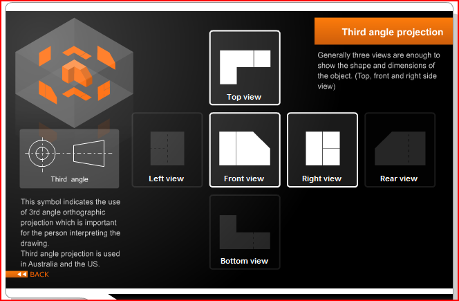
Note the donut 'symbol' for first and third angle projections.
 This is important information for the person interpreting the drawing because in third angle projection:
the view from the front is in the middle
the view from the left is on the left
the view from the right is on the right
the view from the top is on the top
the view from the bottom is on the bottom
the view from the rear is on the far right
BUT with first angle projection, the view you are looking at is projected through to the other side of the object.
So if we are drawing the three visible sides of the object illustrated in a first angle projection, we draw the views projected on the other side of the object and not the three nearest views.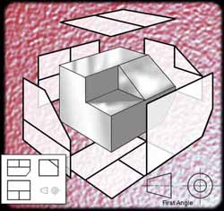

-
Of course just writing what each view is beneath it is the idiot-proof method in case someone reads the plan as the front elevation, or the back as the front etc...
-
Did you not find me paper cup idea novel enough?

-
I did get the cup analogy but I wasn't sure the others would !
-

It's aimed at children really. But that explanation you posted is spot on.
However I'm still at a slight loss how architects use projection. I'll have a look at my genius little Charlotte Baden-Powell book. See what she says.

Hello! It looks like you're interested in this conversation, but you don't have an account yet.
Getting fed up of having to scroll through the same posts each visit? When you register for an account, you'll always come back to exactly where you were before, and choose to be notified of new replies (either via email, or push notification). You'll also be able to save bookmarks and upvote posts to show your appreciation to other community members.
With your input, this post could be even better 💗
Register Login


Advertisement