[Plugin][$] Curviloft 2.0a - 31 Mar 24 (Loft & Skinning)
-
Me too. It's great. I need to learn more of the tricks. I have no idea what the colors and tags mean. By watching videos I get some idea that if you press the different icons sometimes good things happen. But there's math there that I may never comprehend...
" I spent 4 hours manually redrawing almost all of it by deleting multi-segmented but straight lines, redrawing them as 1 line, and reconnecting the endpoints into the mesh"
JGB. Don't tell me you could have used "remove lonely vertices" and didn't?
-
@jgb and pbacot
Thanks for the feedback. Yes Curviloft is still missing many things and this is why it is still in Beta. I have a long list of improvements, including those you mentionned (like equalization of vertex matching) and also a clean up of the different methods, as some were just experimental.
-
for vertex matching, try to have curves with equal number of vertices, that will make the match easier
-
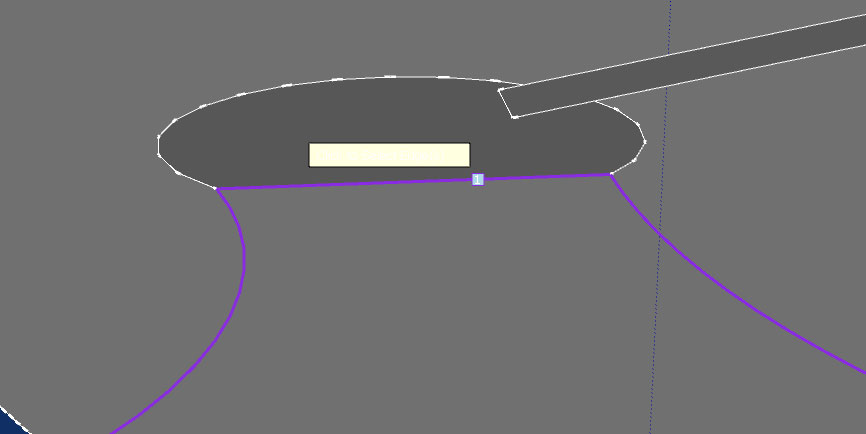
for contour selection, I documented the principles in Curvizard manual. Colors are used simply to distinguish different contours as they may be contiguous. The numbering is to indicate the order of contours, which does matter for Loft by Spline and Loft Along Path.
Fredo
-
-
Thanks for the reply Fredo. (Pbacot... please see below)
I realize that having equal vertices on opposite defining curves will reduce the lines count, but most times that may not be possible, especially with 3 sided contours.
I documented the principles in Curvizard manual --- What is that and where do I find it?
I've leaned that where some curves change color mid contour, or the selection ends at a vertex mid contour there is a problem, usually, but not always. And by the same token, may mean nothing.
I still believe that it would be relatively easy to implement highlighting a problem vertex, gap, line fragment or co-incident edge much the way Solid Inspector does.
Curviloft does find these errors and stops the surface generation, so isolating the error is a non-issue.
You could then color code the problems with a meaningful color selection. For example:
A single orange line is a double co-incident line.
A blue line and adjacent green line means a gap was found between them.
A red line could be an extraneous line at a vertex.
The rest of the contour selected stays black.These make up almost all of the known (to me) types of errors CL finds during a contour check. It would take literally seconds for me to fix knowing what and where they are, instead of long minutes checking almost every line and vertex in the failed contour, and repeating several times the contour selection.
Pbacot;
JGB. Don't tell me you could have used "remove lonely vertices" and didn't?Never heard of that.... Please tell me more.
There is a lot in SU I have never used nor even explored, even after 4 1/2 years using and loving SU. I even have a bunch of plug-ins loaded I almost never use, mostly because I forget they are there.
-
@jgb said:
I realize that having equal vertices on opposite defining curves will reduce the lines count, but most times that may not be possible, especially with 3 sided contours.
Currently, Curviloft respects all vertices of the contours, as these contours could be embedded in the model. Indeed, Curviloft could manage a better placement and matching if it could draw the contours differently.
@jgb said:
I still believe that it would be relatively easy to implement highlighting a problem vertex, gap, line fragment or co-incident edge much the way Solid Inspector does.
Curviloft does not detect errors in selection, as it is unaware of what you wish to do.
What curviloft guarantees is that if you select edges and they are adjacent, forming a single contour, then they get the same color and number...until you validate the contour (blue arrow).At surface generation, Curviloft just traps errors but has no clue of the underlying topology generating the errors.
I think your problem could deserve a dedicated plugin, say Contour Inspector, separated from Curviloft (as contours are used in many plugins).
@jgb said:
Pbacot;
JGB. Don't tell me you could have used "remove lonely vertices" and didn't?
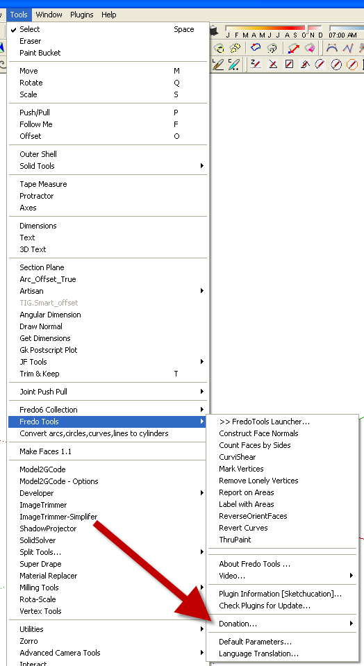
Never heard of that.... Please tell me more.RemoveLonelyVertices is part of FredoTools. Here is the main post
Fredo
-
Fredo; thank you for the explanation.
The underlying reason I am having so much trouble forming curved surfaces lies NOT with Curviloft.
I create fairings and other curved surfaces for my airplanes (and other stuff). The shape of the fairings edges are totally dependent on the surfaces they mount to. This almost always, requires that I make an intersection with the base surface to a curve that forms the general shape of the fairing. So I have a curve intersecting a curve to get the line that will form a side of my fairing, or the contour that CL will use.
SU's intersect usually creates a mess of tiny fragments and gaps when 2 curved surfaces intersect. Most of the fragments and lines are around .001-.004 in, impossible to see. In some cases where I had a vertex with 4 lines, after Intersect I end up with at least 1, sometimes as many as 5 fragments attached to the vertex, and dividing any of the original lines. In some cases, a tiny gap forms. I find that doing a left2right select over the vertex will catch the fragments, but not the gaps. Delete all and many faces will disappear. I then delete all but one line to give me (hopefully) an original endpoint, then redraw the triangles. That will cure the gaps as well.
However, 2 things usually happen when I do that. Some vertices become out of plane and I get a myriad of hidden lines forming on attached faces, or the other end of the intersect line has a fragment that interferes with the forming of the face, forcing a redraw at that vertex, and so-on.
You can see why finding and fixing those fragments & gaps can take me a long time to do, if I have to literally redraw almost every line that is in contact with the intersected line.
It's when the intersect seems to be clean and I apply CL to the fairing perimeter, that my trouble starts, because of those fragments and gaps.
A standalone contour inspector would be very handy, as part of your tools, and as you said, very useful in other SU operations.
As for your "lonely vertices" tool, I've downloaded it, and will install it, and some other tools, real soon now.
-
Maybe you culd post or PM a model so that I can see what a Contour Inspector could do to improve the drawing and junctions of lines.
Fredo
-
@unknownuser said:
Maybe you culd post or PM a model so that I can see what a Contour Inspector could do to improve the drawing and junctions of lines.
Fredo
I can do that.
I have to go back a few versions to give you what I first had to contend with. My current model of an airship has all the fragmented curves fixed (manually) and other than show you the desired end result, you won't find any problems to work with. But I will include them as well. Please give me a few days to set up an SU file with annotated examples.
-
Fredo,
I haven't forgot this. On Sunday I posted an example SKP with a long explanation of what I did. I just checked back to see if you posted a reply yet, and Lo.... the post has disappeared.
I'll re-post tomorrow morning. Head is in the wrong space to do it now.
-
Finally had the chance to re-post this. The "Ole' Battleax" preempted my yesterday.
The purpose of this post is to show Fredo where Curviloft creates excess lines and faces within a relatively simple low poly contour.
The SKP contains 2 bulkheads (out of 12) from my large cargo Airship concept.
The AFT Bulkhead was one of the more complex ones, so I did it first.It was a complex set of steps to create a curved fillet between the bulkhead and the hard carbon fiber aerodynamic skin. The curved fillets serve 3 main purposes.
Spreading the flight loads from the hard skin to the bulkhead,
Forming a smooth rounded corner where the helium bags meet the structure when filled, and
Forming a channel for the helium between bags and compressed He storage tanks.It requires over 15 steps (in 6 major steps) to create a bulkhead, and the Curviloft skin fillets. Typically a bulkhead will require 30 Curvilft skins, plus a pile of manual development. It now takes over a full day to do one, but 7 of the 12 are the same, so I only have 6 to do. But there are also 13 different additional longitudinal frames to do in a similar fashion.
If Curviloft could optimize the face/line generation, then it would take half that time.
And it is NOT just the esthetics of the curve at issue here, In many cases, especially in this model, there will be intersections and cuts to formed surfaces where other parts of structure and systems cross or join. Because SU's Intersect creates significant tiny line fragments, co-linear lines, and co-planar faces especially where curves intersect, reducing the CL lines and face count becomes critical because it takes hours to fix that mess.
In 2 cases in this model alone, I have scrapped parts after it was impossible to fix and tried again, several times. In one case, forming a solid from several intersections of curves, even Solid Solver threw up and totally blew up the object. It took 3 full days to recreate it and make solid manually.
The bulkhead process is detailed in the SKP, so please use LAYERS to see each one, with annotations.
There are 2 bulkheads shown, and one, the aft bulkhead is shown step by step how it was created. The examples (#1 - #5) are not exactly as I did the model, as that bulkhead was almost completed when this post first came up. Most of the contour definition lines had been deleted, so I had to partially recreate the initial steps; however #6 and the fwd bulkhead ARE taken directly from the airship model.
The FWD bulkhead is in RAW condition, equivalent to example #5. Its shape and size are far more consistent with most of the rest of the bulkheads than is the Aft bulkhead.
The other issue of "Contour Inspector" to highlight sources of generation errors will be addressed later when I (WILL) get another major problem.
-
I had a quick look at the model and the steps.
It appears that most of the problems (those highlighted in red) are related to the "equalization" of contours to avoid small segments, collinear edges, etc... As said, Curviloft takes as a constraint all vertices of the contours.To cleanup the contours, you could:
- visualize the vertices with FredoTools::MarkVertices
- simplify the contours with Curvizard::Simplify, which will remove collinear edges, small segments when quasi-aligned
I am going to publish soon an additional tool in Curvizard which will smooth the contours. It performs some cleanup and allow getting a better distribution of vertices.
However, nothing magical, it all depends on how accurate you wish to keep the contours, so that a global clean up would be difficult.
Below is a quick attempt to simplify the contours in step 5
- first the surface you generated
- second the surface after a "Simplify" of the upper contour
- the same surface with generation of interpolated contours to make it smoother.
Fredo
-
Fre-DO! Fre-DO! Fre-Do! Fre-DO! Fre-DO!!!!!!
-
Thanks Fredo;
I guess I gotta load and learn your "Tools" plugin.
In this model, I have no intention of making the curves smoother. It is a concept model, and already too detailed from what I had planned. I'm trying to keep the lines count down. It just broached 100,000 and I'm only about 1/3 done. When I approach 350,000 and over, my beast slows down and autosave takes too long for my liking.
But I can see using additional smoothing in some other models.I have some other curves that caused grief with too many lines & faces. I will attempt to recreate the nose section that was generated in about 5 minutes, but took 4 hours to clean up. The tail section took about double that. That said, it would have taken a week or more to generate each without Curviloft, so I'm not dissing CL; just asking if it can be improved a bit.
-
Hi, I am trying to use this great plugin, but i get the errors as shown in the attached jpg. I have followed the instructions but need help.
As suggested I have the following;
C:\Program Files\Google\Google SketchUp 8\Plugins- LibFredo6.rb
- LIBFREDO6_Dir_46
- CURVILOFT_Dir_12
Thanks in advance.
-
It looks like the same issue that has been covered repeatedly here. You haven't correctly installed the files into the Plugins folder. Correctly installing them includes giving yourself full administrative rights for that folder.
-
plugin doesn't work. it's not visible under "tools > fredo6 collection"
can you help me about it?
-
@compu said:
plugin doesn't work. it's not visible under "tools > fredo6 collection"
can you help me about it?
If you glance back through some of the recent posts in this thread, you'll see that many users can mis-install such tools, or forget to install the supporting Lib set that is clearly indicated and linked in the tool's download page.
Another common error - even after successfully installing the required files and subfolders of files etc - is not realizing that some tools like this need an initial activation as an Extension under the Preferences dialog.
This should then include it in any menu items etc; however, you might need to also activate its toolbar under the View > Toolbar entry to see/use that... -
Fredo,
Curviloft will simply not skin this contour.
It is (or is almost) flat and very similar to about 30 other contours, that skinned with little or no problem where the contours did not flat face with SU's "Face" function.
I have checked every line for doubles, fragments and gaps (none).
I have redrawn most of the lines endpoint to endpoint, especially at junctions.It will form a face if I manually face it, but not with CL.
Could you please tell me why it fails and how you found whatever error I made in it?
[mod=MODERATOR NOTE:3oodv4kq]Removed unnecessary and tiresome overuse of smilies/capitalization.[/mod:3oodv4kq]
-
Joel
You have just managed to contrive a set of almost coplanar edges, and then combine some of them into curves, but then with some that are not... at which CL baulks.
Unsurprisingly!
With a very little adjustment my EEbyRails managed to mesh it - and I freely admit Fredo's tools often has better results than mine do!
My solution works almost instantly - either with the original parts [left] or a more logical/symmetrical split, with an added 'mid-curve' [right].You cannot expect any tool that is in a beta phase, and that is given away freely, to always do what you hope of it - no matter how good it normally performs.
As the original form's author it's up to you to devise a workaround when all else fails.
It took me just a few moments - and of course I care diddly-squat about your project - so surely you could have applied a few of your own brain-cells to come up with a solution to suit your needs...
-
You ccan check that the lines are not coplanar with the section tool. My attempt to solve this... (OK, TIG was faster, Unsurprisingly!)
-
It is not flat. It contained 3 lonely verts. As TIG mentions you seem to not use this tool correctly on a regular basis.
Proper lofting requires an understanding of the lofting process which is heavily covered in Fredo's videos.
Use of 'breaker' edges are needed at times to let Curviloft know what you are trying to loft.
Advertisement