[Plugin][$] Curviloft 2.0a - 31 Mar 24 (Loft & Skinning)


-

Great! A useful plug-in
-
Hey Fredo, I have a file here with some geometry that gave me a hard time -- and I also have some examples of how I got it to work to a tolerable level but certainly not what I had envisioned.
I'm sure user error was responsible to a degree but I though I'd share it with you if it helps debug at all.
Best,
Jason.
-
@jason_maranto said:
Hey Fredo, I have a file here with some geometry that gave me a hard time -- and I also have some examples of how I got it to work to a tolerable level but certainly not what I had envisioned.
I'm sure user error was responsible to a degree but I though I'd share it with you if it helps debug at all.
Best,
Jason.Jason,
Thanks. This is a good example which shows some limitations of Curviloft (and it's not your errors at all!).
You probably have to do it in 2 parts, as you did. First part should be with the option 'Line junction' and second part with Cubic Bezier, but you should simply skip the last profile before the rear face of the hull.
Alternatively, you can take some inspiration of what it could give with the two other methods: Skinning and Loft along Path.

In any case, I would suggest that you redraw the long profile to show more continuity at the junction(maybe with a single piece of spline).Fredo
-
Thank-you again... that was very helpful and led me in a different direction that worked much better.
I have another file for you -- I suspect this is asking for too much

Best,
Jason.
-
@jason_maranto said:
I have another file for you -- I suspect this is asking for too much
Jason,
This is definitely too much for Curviloft. The only way to achieve it on this kind of model is to draw intermediate profiles and use Skinning.
Indeed, you have to figure out how these intermediate profiles should be. But anyway, there are so many solutions to skin your shape that any program would need some guidance.
Fredo
-
Thanks Fredo, this is all magic to me -- so many of the things Curviloft can do didn't seem possible in Sketchup to me just a few weeks ago... I might have gotten a bit carried away by your wizardry

I did get it to skin in a few configurations but nothing I was completely satisfied with.
BTW I have noticed on my system that has an ATI Firepro (workstation video card) the vertex matching function is very temperamental -- when I switch to my system that uses a Nvidia Quadro it is very smooth.
Best,
Jason. -
@jason_maranto said:
BTW I have noticed on my system that has an ATI Firepro (workstation video card) the vertex matching function is very temperamental -- when I switch to my system that uses a Nvidia Quadro it is very smooth.
Visual glitches?
If so - screenshots? -
I'll record a video example when I get to the studio.
Best,
Jason. -
hi! your plugs are really more than better and usefull
many THANX! -
Here's a video showing the issue:
Took down the link to conserve bandwidth
Best,
Jason. -
Just installed Curviloft into my SU8 and am excited as all hell about the possibilities!
One question: I need to apply a directional material (wood grain) to the new surface. It applies the pattern to each individual facet, sometimes in the wrong direction. How do I change the pattern direction on a Curviloft surface?
Okay another question: what exactly is the Sketchup structure of a curviloft surface? Can I explode it?
Thanks!...and good job on the plugin!
-
It comes in as a group and yes, you can explode it. Turn on hidden geometry (View menu) to se the structure.
As for texturing it, you need to apply the texture to the surface itself (groups with curved geometry cannot be textured from outside without the texture being applied chaotically). Even on the surface, most probably you need to turn on hidden geometry, apply the texture on one facet; position it then sample and apply on the other facets. Depending on the complexity of the shape, it may take a while - or you can use some UV mapping tool for it.
-
By the way, I normally fixed this issue of coplanar contours on the horizontal plane in Curviloft 1.1.
This was signaled by Pilou with a workaround by Diego-Rodriguez
Fredo
-
thank goodluck
-
Fredo,
I don't know if this has already been discussed, but there seems to be an issue with "loft junctions following two paths". I create a shape using bezier curves and then convert them to polyline dividers. The script does a really nice job making the overall shape, the problem is along the seam where the profiles meet. It may be due to a mismatch in the number of segments in the edges from one side to the other, but Curviloft creates extra faces that are "folded" into the geometry and are essentially invisible until one goes in and starts moving verts around. The cause a visible seam to show up when shaded smooth. The only solution I know of is to go through and find each face and reconnect/rebuild each edge and face to remove them. Any suggestions on how to better avoid this extra work? Is it as bug or simply an issue with my modeling?


Thanks for all your hard work!
-
@escapeartist said:
Fredo,
I don't know if this has already been discussed, but there seems to be an issue with "loft junctions following two paths". I create a shape using bezier curves and then convert them to polyline dividers. The script does a really nice job making the overall shape, the problem is along the seam where the profiles meet. It may be due to a mismatch in the number of segments in the edges from one side to the other, but Curviloft creates extra faces that are "folded" into the geometry and are essentially invisible until one goes in and starts moving verts around. The cause a visible seam to show up when shaded smooth. The only solution I know of is to go through and find each face and reconnect/rebuild each edge and face to remove them. Any suggestions on how to better avoid this extra work? Is it as bug or simply an issue with my modeling?
Would have the model so that I can have a look.
This seems strange, but Curviloft algorithms have some shortcuts for performance reasons which may explain a few issues like this one.Thanks
Fredo
-
@EscapeArtist:
That second image looks like rather than "extra" reversed faces, you have pulled the mesh somewhat inside out because additional edges need to be placed. The additional edges would be placed only in order to get additional vertices. Adding edges will avoid seam ripping which is what appears to be happening here.
I am just saying this from my experience with detail "knitting" on meshes.
Of course, I am probably wrong.. again -
@mitcorb said:
@EscapeArtist:
That second image looks like rather than "extra" reversed faces, you have pulled the mesh somewhat inside out because additional edges need to be placed. The additional edges would be placed only in order to get additional vertices. Adding edges will avoid seam ripping which is what appears to be happening here.
I am just saying this from my experience with detail "knitting" on meshes.
Of course, I am probably wrong.. againThe model is as-is Curviloft output, the pulling was done in order to reveal the extra edges and faces. The face isn't visible until the vert is pulled out of alignment because the edges are so close together as to appear to be a single edge. I did re-stitch the seam and it looks OK but for the slight ripple created by my inability to precisely match the desired curvature by hand.
Fredo, the model and curves are attached.
-
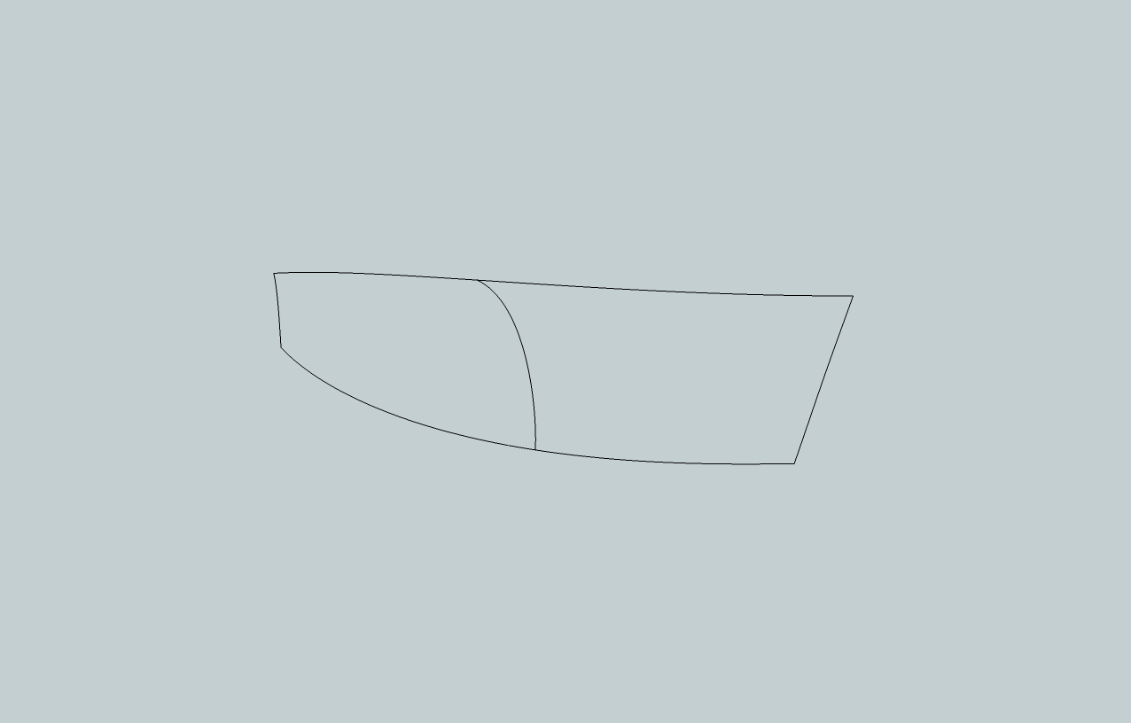
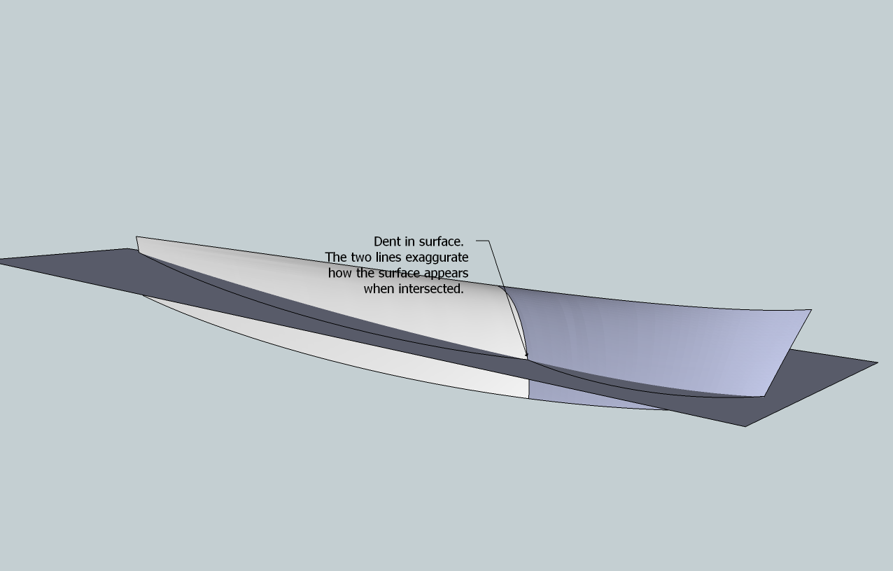
Dear Fredo6. I use curviloft extensively (for boat design purposes) and am very grateful for it. But there is an issue that I would like to address: When making hull sides for boats, I create two compound curves. You can see it in the attached images. The upper line is the deck- line, the lower one is the so- called chine. The left side is where the transom is, the right side is the stem. In the middle, there is a line that defines a flare in the bow- sections of the boat. Ideally, Curviloft would create a smooth panel from these lines, but no matter how I do it (skinning, path or lofting), Curviloft seems to do it in a different way than expected, the result being a dented surface.
For example, if I selected the middle line first or last, I would expect a different outcome then when it is selected subsequently from left to right or vice versa. Curviloft seems to think of it like two surfaces instead of one, just like the colors indicate. Occasionally the color is the same for the whole panel, but it still appears to be dented.
I may be asking too much of Curviloft, but if there is a way that I have not detected yet, then I would appreciate that.
PS I have installed latest (January 2011) versions of Curviloft and Libfredo
Best regards Teo
-
Hi All
Been using this for only a few days and its great
Now i'm trying some more tricky shapes with odd results
On a simple shape i click on each line and it comes up 1,2,3,4 and skins
Then sometimes I click and it comes up 1 with an orange line, next line 1 again and orange and so on. When I click the green tick all the lines turn purple
Does this mean its too much for CL?
Thanks
Hello! It looks like you're interested in this conversation, but you don't have an account yet.
Getting fed up of having to scroll through the same posts each visit? When you register for an account, you'll always come back to exactly where you were before, and choose to be notified of new replies (either via email, or push notification). You'll also be able to save bookmarks and upvote posts to show your appreciation to other community members.
With your input, this post could be even better 💗
Register Login


Advertisement